Eureka AIR delivers breakthrough ideas for toughest innovation challenges, trusted by R&D personnel around the world.

A manufacturing process of a combined heat dissipation structure for a transformer

A technology of heat dissipation structure and manufacturing process, applied in the field of transformers, can solve the problems of high manufacturing cost and complicated manufacturing process of heat dissipation structure, and achieve the effect of convenient post-assembly, guaranteeing use effect and use efficiency, and novel structure.

Active Publication Date: 2019-06-21
安徽金环电气设备有限责任公司
View PDF6 Cites 0 Cited by
  • Summary
  • Abstract
  • Description
  • Claims
  • Application Information

AI Technical Summary

Problems solved by technology

The heat dissipation structure plays a very important role in the transformer. The traditional heat dissipation structure of the transformer has complicated production process, high production cost and great limitations. Now there is a lack of a transformer insulation pad and its production process to solve the above problems

Method used


Image

  • A manufacturing process of a combined heat dissipation structure for a transformer
  • A manufacturing process of a combined heat dissipation structure for a transformer
  • A manufacturing process of a combined heat dissipation structure for a transformer

Examples


Embodiment Construction

[0026] The following will clearly and completely describe the technical solutions in the embodiments of the present invention with reference to the accompanying drawings in the embodiments of the present invention. Obviously, the described embodiments are only some, not all, embodiments of the present invention. Based on the embodiments of the present invention, all other embodiments obtained by persons of ordinary skill in the art without making creative efforts belong to the protection scope of the present invention.

[0027] In the present invention, it should be noted that the terms "center", "upper", "lower", "left", "right", "vertical", "horizontal", "inner", "outer" etc. indicate The orientation or positional relationship is based on the orientation or positional relationship shown in the drawings, and is only for the convenience of describing the present invention and simplifying the description, rather than indicating or implying that the referred device or element mus...


PUM

PropertyMeasurementUnit
thicknessaaaaaaaaaa
thicknessaaaaaaaaaa
depthaaaaaaaaaa

Abstract

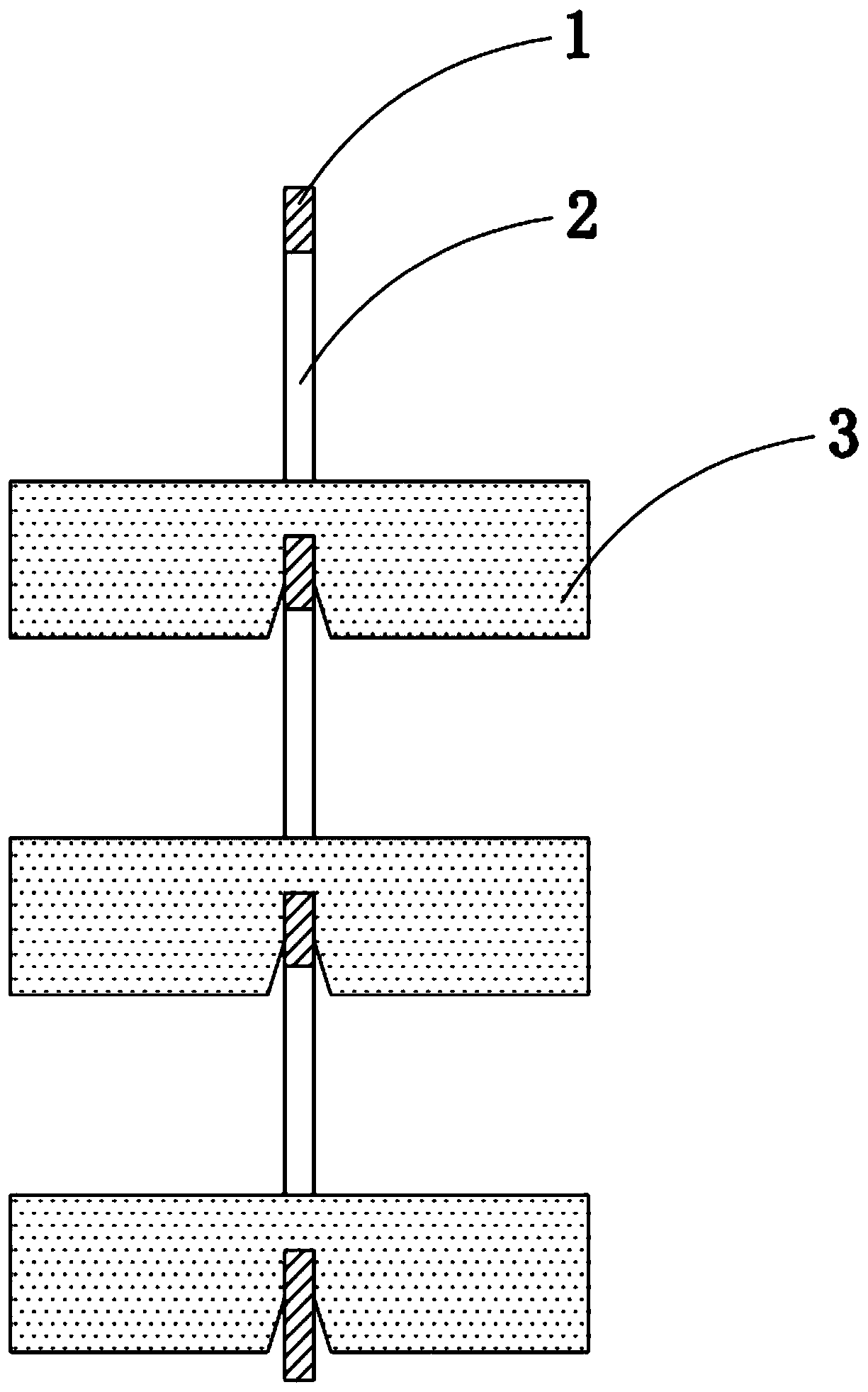
The invention discloses a combined-type heat radiation structure used for a transformer. The structure comprises a vertical board. Through holes are uniformly arranged in the vertical board. Radiatingfins in snap joint with the vertical board are arranged in the through holes in a penetrating manner. The radiating fins are equipped with clamp grooves corresponding to the through holes. The overall heat radiation structure of a conventional transformer is changed. The through holes are uniformly arranged in the vertical board such that the radiating fins in snap joint with the vertical board are arranged in the through holes in the penetrating manner. The vertical board and the radiating fins are all copper aluminum alloy boards which hare low in cost and good in heat radiation performance. Manufacture process is optimized. Openings of the clamp grooves are equipped with chamfers in order to facilitate assembling in the late period. Polishing treatment comprises coarse grinding and precise grinding treatment such that burr and scraps on surfaces are processed clean, which is convenient for subsequent installation. Planeness errors of the vertical board and the radiating fins are nobigger than + / -0.01 mm so that assembly quality is increased. The combined-type heat radiation structure is simple in process so that the overall heat radiation area is increased. The heat radiationperformance is improved. The combined-type heat radiation structure shows great practicality.

Description

technical field [0001] The invention relates to the technical field of transformers, in particular to a manufacturing process of a combined heat dissipation structure for a transformer. Background technique [0002] After 1870, with the widespread application of electricity, science and technology developed by leaps and bounds, and various new technologies and inventions emerged one after another, and were quickly applied to industrial production, greatly promoting economic development. With the continuous development of my country's economic construction and the acceleration of urbanization, electricity has become an indispensable part of people's production and life. At present, my country's main source of electricity is thermal power generation, which utilizes the heat energy generated during the combustion of solid, liquid, and gaseous fuels such as coal, oil, and natural gas, and converts it into electrical energy through power generation devices. With the rapid develo...

Claims


Application Information

Patent Timeline
Patent Type & Authority Patents(China)
IPC IPC(8): H01F27/22B23P15/26
CPCB23P15/26B23P2700/10H01F27/22
Inventor 马书龙刘三才
Owner 安徽金环电气设备有限责任公司
Why Eureka
Eureka Blog
Learn More