flywheel engine

A technology for engines and flywheels, which is applied to combustion engines, engine components, flywheels, etc., can solve the problems of large fuel adaptability, many moving parts, and small adaptability, and achieve large fuel adaptability, low speed requirements, and easy maintenance Effect

Active Publication Date: 2021-03-02
李久斌
View PDF6 Cites 0 Cited by
  • Summary
  • Abstract
  • Description
  • Claims
  • Application Information

AI Technical Summary

Problems solved by technology

[0003] The purpose of the present invention is to solve the problems that most of the existing heat engines are composed of cylinders, pistons, connecting rods, crankshafts, flywheels, etc., with many moving parts, complex structures, large vibrations, high noises, and small fuel adaptability. Provide a flywheel engine, which uses working fluid to directly drive the flywheel, has simple structure, large torque, low noise, and at the same time, the adaptability of fuel is large, and the heat energy can be recycled repeatedly. It can be combined with a four-stroke engine to form a combined engine, which greatly improves fuel consumption Utilization of

Method used


Image

  • flywheel engine
  • flywheel engine
  • flywheel engine

Examples


Embodiment 1

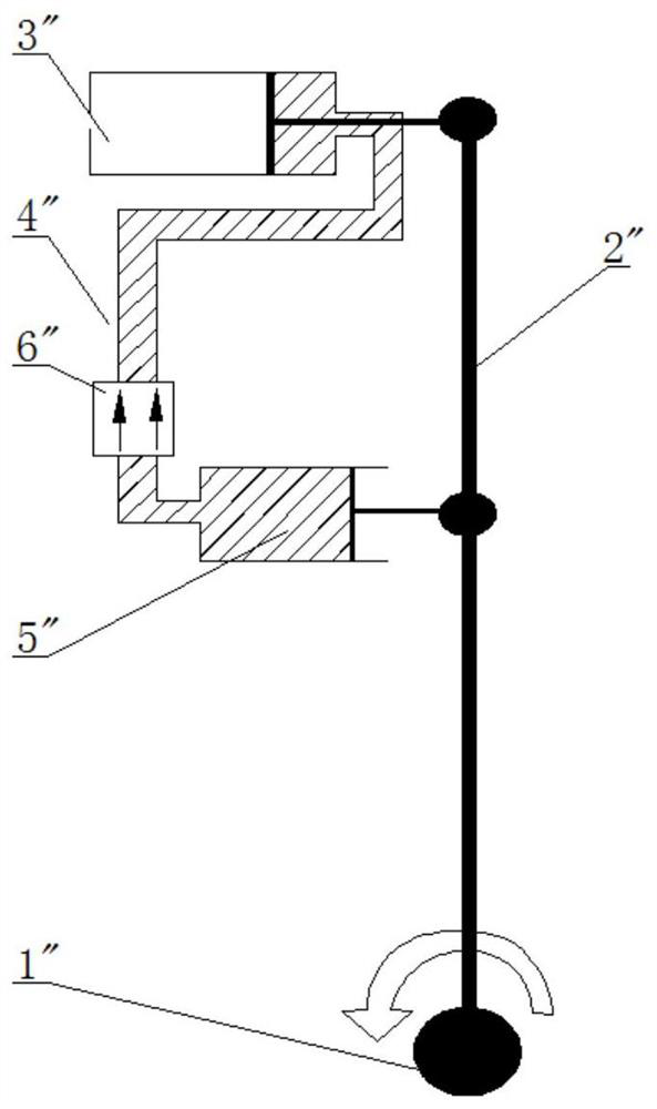
[0035]A kind of flywheel engine of the present invention, it comprises working chamber 1, suction chamber 2, air duct 3, central axis 4, and each said working chamber and suction chamber are respectively made of flywheel 100, flywheel housing 101, flywheel cover 102, gas brush 103 composition;

[0036] The flywheel engine of the present embodiment installs two flywheels to form a double-wheel mode, see figure 2 , the flywheel engine has a work chamber and a suction chamber, the flywheel engine also includes a combustion heating chamber 5, and the outlet end of the suction chamber is also provided with a valve for preventing the working fluid from flowing back into the suction chamber from the heating pipe One-way air valve, the working chamber, the suction chamber, and the combustion heating chamber are connected through an air guide tube. The two flywheels in this embodiment are respectively arranged in the working chamber and the suction chamber, and the working chamber has...

Embodiment 2

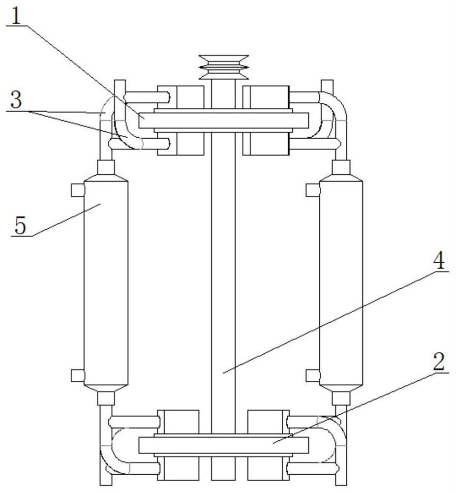
[0042] The flywheel engine of the present embodiment is a double-cycle mode under the double-wheel mode, a kind of flywheel engine, it comprises working chamber, suction chamber, air duct, center shaft, each described working chamber and suction chamber are respectively composed of flywheel, Composed of flywheel housing, flywheel cover and air brush;

[0043] The flywheel cover is a disc body, the disc body includes a circular ring, and a bearing hole for the central shaft to pass through the middle, the flywheel is a double-wheel mode, and the upper left side of the flywheel cover has a One air intake hole, one air outlet hole on the upper right side, one air outlet hole on the lower left side, and one air inlet hole on the lower right side, and the flywheel cover also has two air brush installation holes;

[0044] The air outlet hole is connected with an air outlet pipe, the air inlet hole is connected with an air inlet pipe, and the flywheel cover is also provided with a sh...

Embodiment 3

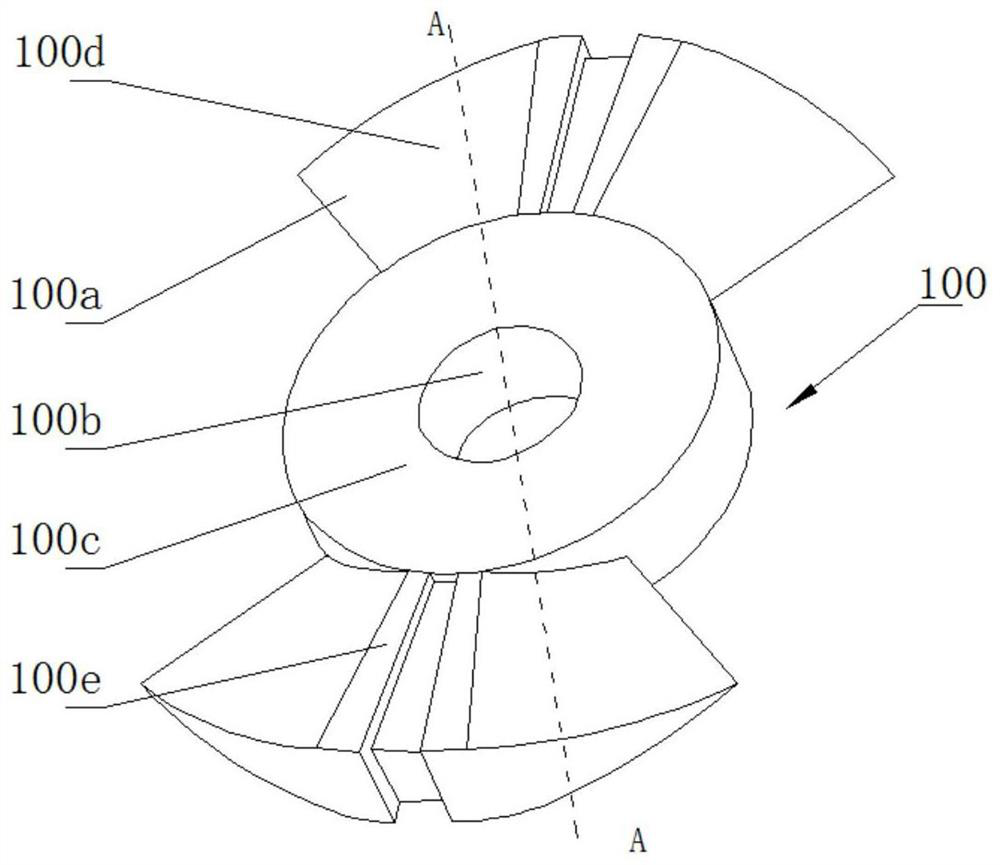
[0050] The flywheel engine of the present embodiment adopts a single wheel mode, and it comprises a work chamber, an air suction chamber, an air duct, a combustion heating chamber, and a central axis, and each said work chamber and air suction chamber are respectively composed of a flywheel 200, a flywheel housing, and a flywheel cover. 201. The composition of the air brush, the structure of the flywheel 200 and the flywheel cover 201 in the single-wheel mode refer to Figure 11 , Figure 12 ; The flywheel is placed in the middle of the flywheel shell, and the two flywheel covers are closed on the left and right sides of the flywheel, and the central shaft passes through the bearing hole of the flywheel cover and is fixed in the flywheel shaft hole.

[0051] The flywheel 200 is a circular wheel structure, and the circular wheel structure includes a first circular wheel sector 200a, a second circular wheel sector 200b, an axle hole 200c for fixing the center shaft, and spokes f...


PUM


Abstract

The invention provides a flywheel engine. The flywheel engine comprises work doing chambers, gas suction chambers, a gas guiding pipe and a central axle. The work doing chambers and the gas suction chambers are each composed of a flywheel, a flywheel shell, a flywheel cover and a gas brush. Each flywheel has a single-wheel mode or a double-wheel mode. Running of work doing gas in the flywheel engine has a single cycle mode and a double-cycle mode. When the flywheel structure is in a double-wheel mode, and running of the work doing gas in the flywheel engine is in the single cycle mode, the flywheel engine is provided with one work doing chamber and one gas suction chamber. The flywheel engine further comprises a combustion heating chamber. The outlet ends of the gas suction chambers are further provided with one-way gas valves used for preventing a work medium from flowing back from a heating pipe to enter the gas suction chambers. According to the flywheel engine, the flywheels are directly driven by using the work medium, the structure is simple, torque is large, noise is small, meanwhile, the adaptive surface of fuel is large, heat energy can be reused repeatedly, the flywheel engine can be combined with a four-stroke internal combustion engine to form a combined engine, and the utilization ratio of the fuel is greatly improved.

Description

technical field [0001] The invention relates to the technical field of engines, in particular to a flywheel engine which uses working fluid to directly drive a flywheel, has simple structure, high torque, low noise, heat energy can be recycled repeatedly, and can be combined with other engines to manufacture a combined engine. Background technique [0002] At present, there are many types of heat engines, most of which are composed of cylinders, pistons, connecting rods, crankshafts, flywheels, etc., with many moving parts, large vibrations, and loud noises. Only fuel and gas can be used, and solid fuels cannot be used. Cylinder heat cannot be recycled, and it is difficult to greatly increase the thermal efficiency of fuel oil; in addition, the operating temperature of gas turbine and turbine engine is too high, the requirements for materials are high, the speed is too fast, the idle speed is high, and the cost is expensive; in short, various types of Engine application rang...

Claims


Application Information

Patent Timeline
Patent Type & Authority Patents(China)
IPC IPC(8): F02B75/40F02B23/00F16F15/30F02B77/00
CPCF02B23/00F02B75/40F02B77/00F16F15/30Y02T10/12
Inventor 李久斌
Owner 李久斌
Why Eureka
Try Eureka