Slurry mixing device for construction site
A technology for mixing equipment and building construction, which is applied in liquid batching supply devices, clay preparation devices, chemical instruments and methods, etc., can solve the problems of inhaling too much irritating odor, inability to fully stir evenly, and the cumbersome and laborious stirring process.
- Summary
- Abstract
- Description
- Claims
- Application Information
AI Technical Summary
Problems solved by technology
Method used
Image

Examples
Embodiment 1
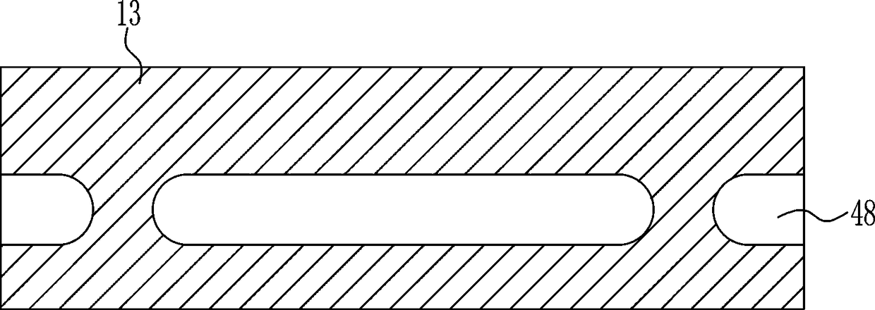
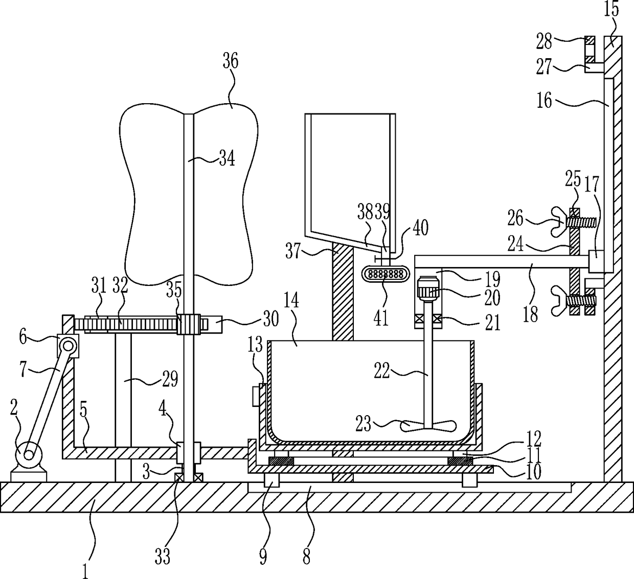
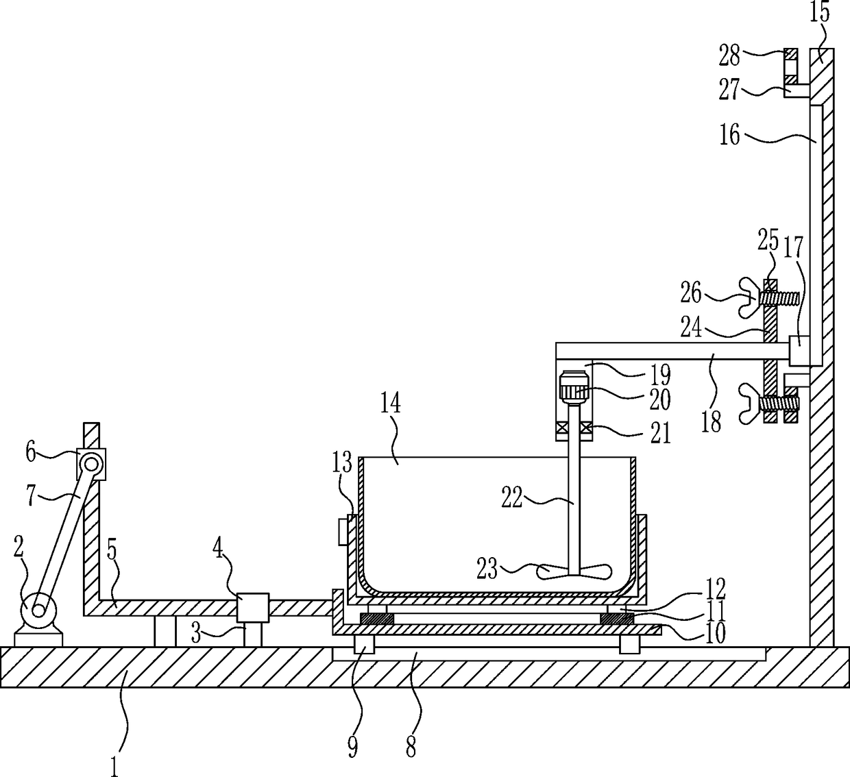
[0027] A kind of slurry mixing equipment for building construction, such as Figure 1-4 As shown, it includes a bottom plate 1, a geared motor 2, a support rod 3, a guide sleeve 4, a moving frame 5, a sliding sleeve 6, a connecting rod 7, a first slide rail 8, a first slide block 9, a mounting frame 10, a ring slide Rail 11, second slider 12, placement frame 13, mixing box 14, right bracket 15, second slide rail 16, third slider 17, support rod 18, mounting plate 19, first motor 20, first bearing Seat 21, first rotating shaft 22, stirring plate 23, fixed rod 24, butterfly bolt 26, fixed block 27 and nut 28, bottom plate 1 is provided with deceleration motor 2 and strut 3 on the left side, deceleration motor 2 is located at strut 3 On the left side, the upper end of the pole 3 is provided with a guide sleeve 4, the guide sleeve 4 is slidingly provided with a moving frame 5, the upper part of the moving frame 5 is slidingly provided with a sliding sleeve 6, and the front part of...
Embodiment 2
[0029] A kind of slurry mixing equipment for building construction, such as Figure 1-4 As shown, it includes a bottom plate 1, a geared motor 2, a support rod 3, a guide sleeve 4, a moving frame 5, a sliding sleeve 6, a connecting rod 7, a first slide rail 8, a first slide block 9, a mounting frame 10, a ring slide Rail 11, second slider 12, placement frame 13, mixing box 14, right bracket 15, second slide rail 16, third slider 17, support rod 18, mounting plate 19, first motor 20, first bearing Seat 21, first rotating shaft 22, stirring plate 23, fixed rod 24, butterfly bolt 26, fixed block 27 and nut 28, bottom plate 1 is provided with deceleration motor 2 and strut 3 on the left side, deceleration motor 2 is located at strut 3 On the left side, the upper end of the pole 3 is provided with a guide sleeve 4, the guide sleeve 4 is slidingly provided with a moving frame 5, the upper part of the moving frame 5 is slidingly provided with a sliding sleeve 6, and the front part of...
Embodiment 3
[0032] A kind of slurry mixing equipment for building construction, such as Figure 1-4 As shown, it includes a bottom plate 1, a geared motor 2, a support rod 3, a guide sleeve 4, a moving frame 5, a sliding sleeve 6, a connecting rod 7, a first slide rail 8, a first slide block 9, a mounting frame 10, a ring slide Rail 11, second slider 12, placement frame 13, mixing box 14, right bracket 15, second slide rail 16, third slider 17, support rod 18, mounting plate 19, first motor 20, first bearing Seat 21, first rotating shaft 22, stirring plate 23, fixed rod 24, butterfly bolt 26, fixed block 27 and nut 28, bottom plate 1 is provided with deceleration motor 2 and strut 3 on the left side, deceleration motor 2 is located at strut 3 On the left side, the upper end of the pole 3 is provided with a guide sleeve 4, the guide sleeve 4 is slidingly provided with a moving frame 5, the upper part of the moving frame 5 is slidingly provided with a sliding sleeve 6, and the front part of...
PUM
 Abstract
Description
Claims
Application Information
 - Generate Ideas
- Intellectual Property
- Life Sciences
- Materials
- Tech Scout
- Unparalleled Data Quality
- Higher Quality Content
- 60% Fewer Hallucinations
Browse by: Latest US Patents, China's latest patents, Technical Efficacy Thesaurus, Application Domain, Technology Topic, Popular Technical Reports.
© 2025 PatSnap. All rights reserved.Legal|Privacy policy|Modern Slavery Act Transparency Statement|Sitemap|About US| Contact US: help@patsnap.com