
Jet laser composite cleaning method and cleaning system

A cleaning system and jet technology, applied in the field of jet laser composite cleaning method and cleaning system, can solve the problems of limited cleaning force, secondary pollution, inconvenient cleaning and clamping of workpieces, etc. The effect of prolonging the effective time of action

Pending Publication Date: 2018-09-14
GUILIN UNIV OF ELECTRONIC TECH
View PDF8 Cites 9 Cited by
  • Summary
  • Abstract
  • Description
  • Claims
  • Application Information

AI Technical Summary

Problems solved by technology

Workpiece clamping is inconvenient and cleaning is also inconvenient
[0006] In short, the existing wafer substrate cleaning methods are faced with the problems of limited cleaning power, secondary pollution, and inconvenient cleaning and clamping of the workpiece, and cannot be qualified for the high-demand cleaning of the wafer surface.

Method used


Image

  • Jet laser composite cleaning method and cleaning system
  • Jet laser composite cleaning method and cleaning system
  • Jet laser composite cleaning method and cleaning system

Examples


Embodiment Construction

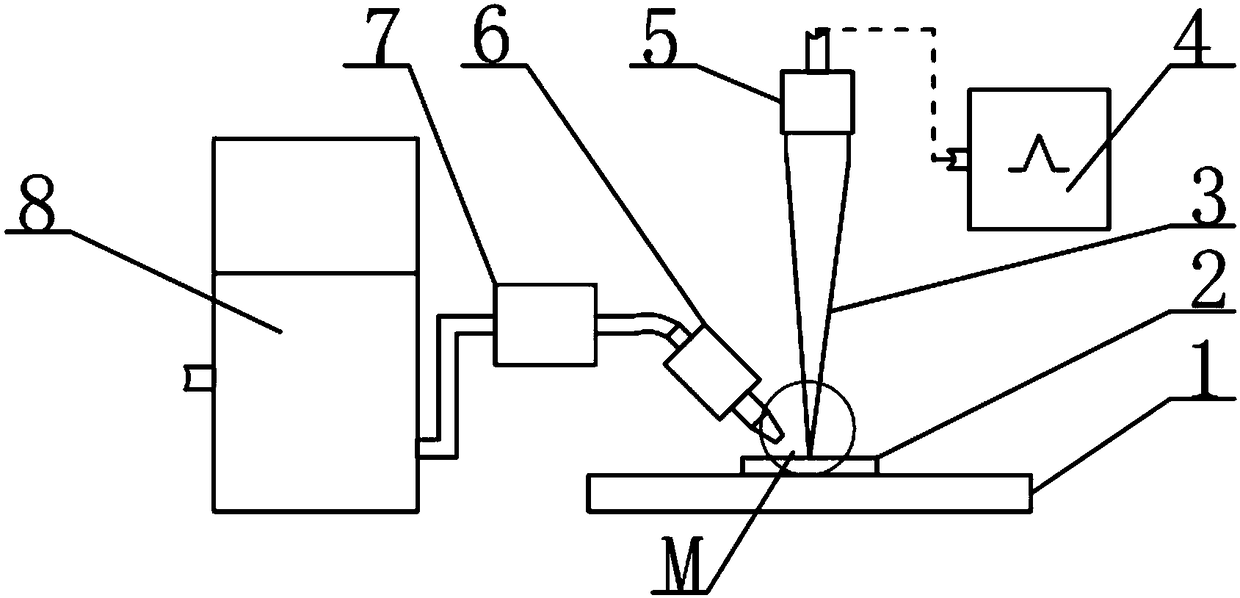
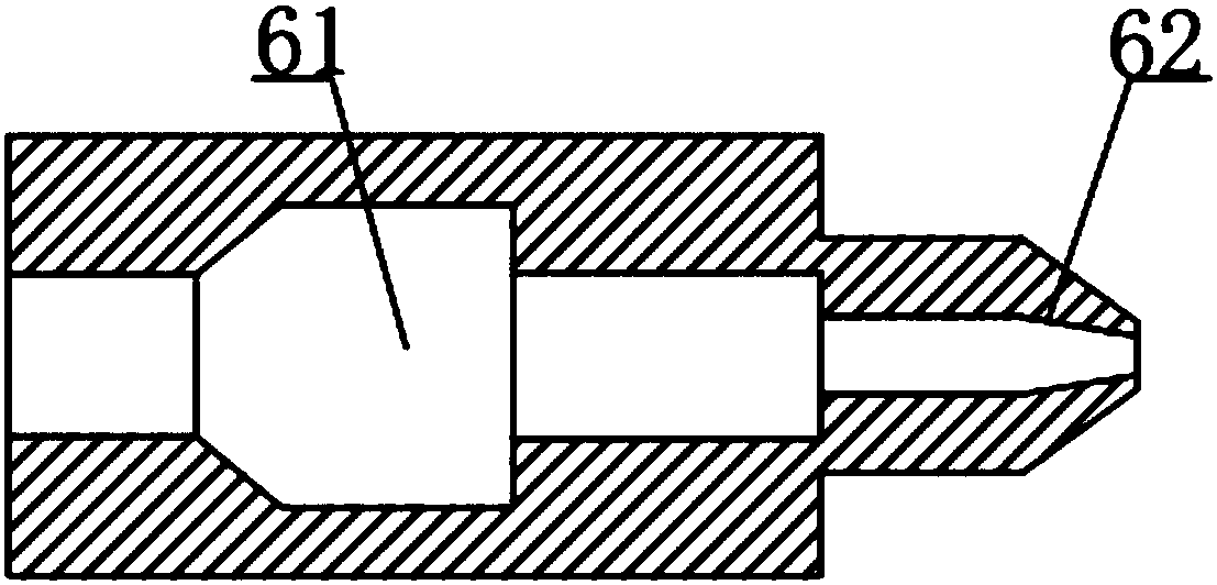
[0026] The structure of the embodiment of the jet laser composite cleaning system is as follows: figure 1 As shown, it includes a water tank 8 , a jet pressurization chamber 7 , a cavitation jet nozzle 6 , a laser 4 and a workbench 1 .

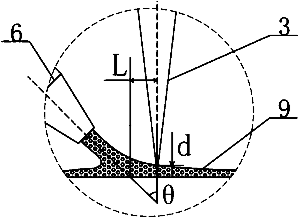
[0027] The workbench 1 in this example is a three-dimensional adjustable workbench with a horizontal surface, and the workpiece 2 in this example is a wafer, which is fixed on the workbench 1 . The outlet pipe of the water tank 8 is connected with the jet pressurization chamber 7, and the outlet of the jet pressurization chamber 7 is connected with the cavitation jet nozzle 6. The water in the water tank 8 is pressurized through the jet pressurization chamber 7, and the high-pressure water flow exits the cavitation jet from the cavitation jet nozzle 6. The laser beam generated by the laser 4 is connected to the fiber laser shaper 5 , and the focal point of the shaped laser beam 3 is in the water film 9 above the workpiece 2 .

[0028] Such a...


PUM


Abstract

The invention relates to a jet laser composite cleaning method and a cleaning system. A water film and a water film cavitation bubble breaking impact cleaning base material surface are generated, andmeanwhile, a laser is focused in the water film, the water film explodes in a super-heating state, the water film is vigorously vaporized, steam bubbles are generated to impact the surface of base materials, and the effective action time of cavitation jet is prolonged. The cleaning system comprises an cavitation jet device and a laser cleaning device; and the laser beam and the center line of thecavitation jet are coplanar, the cavitation jet flow generates the water film on the surface of a workpiece, the laser beam is focused in the water film and keeps a distance from the surface of the workpiece, and the laser beam and the cavitation jet flow act on the surface of the workpiece on a workbench to be cleaned, so that the effect is obviously superior to that of the existing cleaning technology, solid particles with the surface diameter larger than 50 nm can be removed, and the surface processing requirements of the wafer base materials can be met.

Description

technical field [0001] The invention relates to a jet cleaning technology, in particular to a jet laser composite cleaning method and a cleaning system using a cavitation jet. Background technique [0002] With the rapid development of the high-precision semiconductor industry, the requirements for silicon wafers—wafers, which are used to make integrated circuits—continue to increase. The particles attached to the surface of the wafer will block the light of the photolithography process, resulting in deviations in the circuit processing morphology. In order to solve the problem of wafer surface cleaning, chemical cleaning technology and air flow cleaning technology are constantly improving. However, with the development of integrated circuits to high precision, the size of wafer processing features has been reduced to the order of microns. In order to achieve processing accuracy, the maximum size of solid particles attached to the wafer surface is required to be 1 / 10 to 1 / ...

Claims


Application Information

Patent Timeline
Patent Type & Authority Applications(China)
IPC IPC(8): B08B3/02B08B7/00
CPCB08B3/02B08B7/0042
Inventor 刘清原龙芋宏周嘉鲍家定黄宇星赵要武焦辉
Owner GUILIN UNIV OF ELECTRONIC TECH
Learn More