Fountain system

A fountain and filter chamber technology, applied in the direction of spray device, liquid spray device, etc., can solve the problems of single fountain spray effect, unable to complete the neat and consistent adjustment of the nozzle angle, unable to meet the requirements of multi-angle spray, etc., to achieve a wide range of power. , The effect of stable transmission ratio and reduced maintenance rate

Active Publication Date: 2018-09-14
日照新睿招商发展有限公司
View PDF12 Cites 1 Cited by
  • Summary
  • Abstract
  • Description
  • Claims
  • Application Information

AI Technical Summary

Problems solved by technology

[0004] The purpose of the present invention is to provide a fountain system to solve the problems in the above-mentioned background technology. The overall structure of the general fountain is relatively simple, most of the nozzles are fixed, and the angle of the nozzles cannot be adjusted uniformly, so that the spray effect of the fountain Single, can not meet the problem of multi-angle injection requirements

Method used


Image

  • Fountain system
  • Fountain system
  • Fountain system

Examples


Embodiment 1

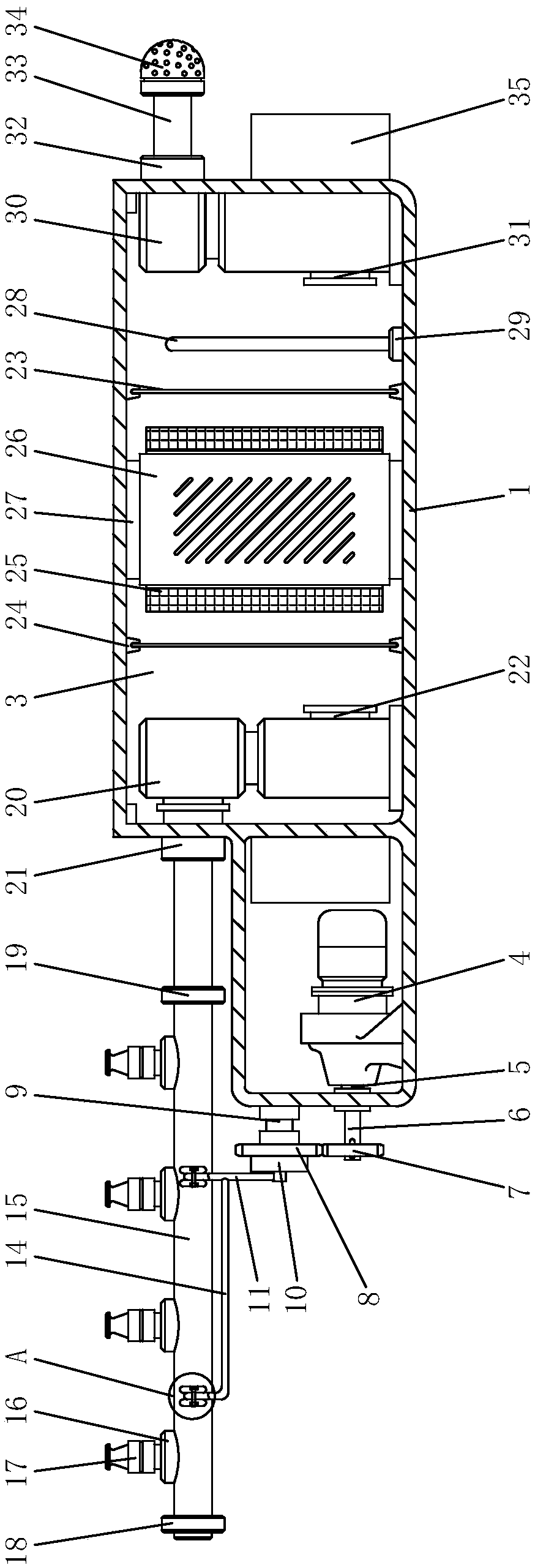
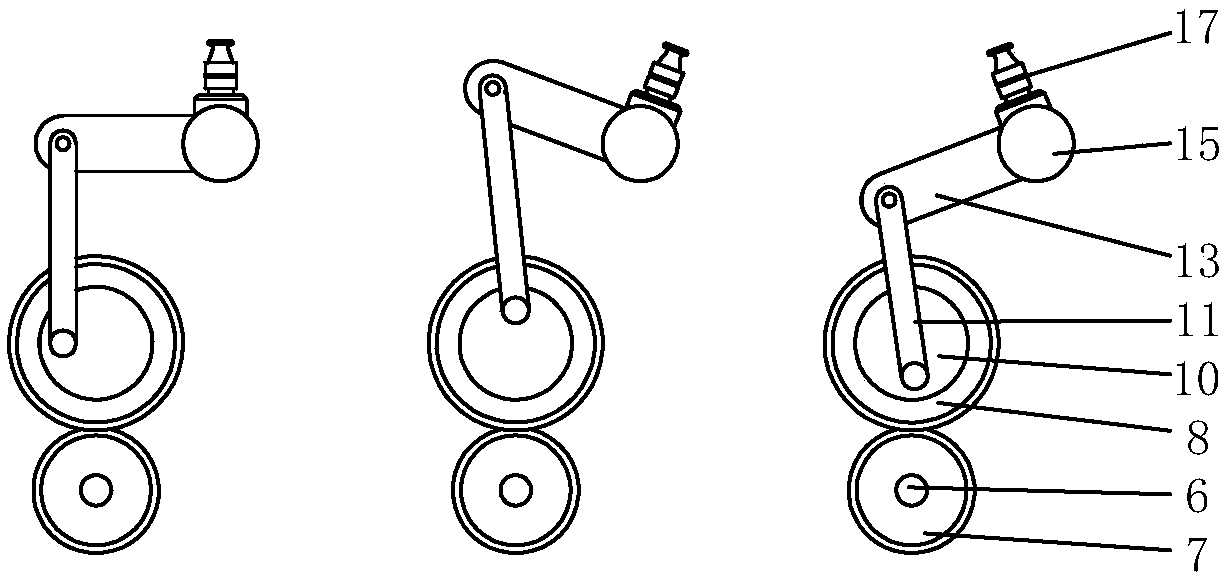
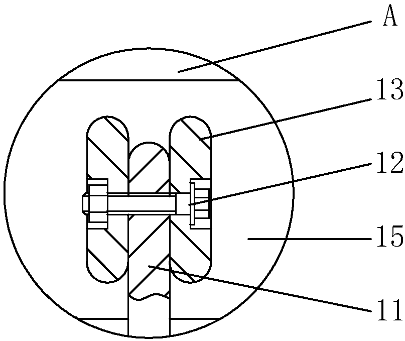
[0046] see Figure 1-3 , the present invention provides a technical solution: a fountain system, including a main body shell 1, an eccentric wheel 10, a branch pipe 16, a pressurizing pump 20, a water level plate 28 and a conversion joint 32, and the inside of the main body shell 1 is respectively provided with a power chamber 2 And the filter chamber 3, and the power chamber 2 is located on the left side of the filter chamber 3, the inside of the power chamber 2 is provided with a motor 4, and the left side of the motor 4 is provided with a sealed bearing 5, and the left side of the sealed bearing 5 is connected to a shaft 6 , and the left end of the shaft 6 is fixed with a driving gear 7, the top of the driving gear 7 is connected with a transmission gear 8, and the right side of the transmission gear 8 is provided with a fixed rotating shaft 9, the shaft 6 runs through the inside of the sealed bearing 5, and the shaft The right end of the rod 6 is integrated with the motor ...

Embodiment 2

[0049] see Figure 4-9, the difference between this embodiment and embodiment 1 is that: the water pump is a diaphragm pump or a plunger pump, and an internal water outlet is provided on the left side of the lower end of the water pump, a water inlet is installed on the right side of the conversion joint, and the conversion joint Located on the upper right side of the main body shell, a filter pump is connected to the right side of the water inlet; the filter pump is not only used to filter impurities, but also cooperates with the water pump to increase the pumping power.

[0050] The filter pump includes a motor 91 , a pump casing 92 and a water wheel 96 rotatably installed in the pump casing and driven by the motor.

[0051] A pump cover 911 is connected to the lower end of the motor, and the pump cover is sealingly connected to the upper end of the pump casing with an open upper end, and a pump chamber is formed between the pump casing and the pump cover.

[0052] The midd...


PUM


Abstract

The invention discloses a fountain system. The system comprises a main body shell, an eccentric wheel, branch pipes, a pressurization pump, a water level plate and a conversion joint, a power bin anda filter bin are correspondingly arranged inside the main body shell, an electromotor is arranged in the power bin, the left side of a sealing bearing is connected with a shaft rod, a transmission gear is connected above a driving gear, movable rods are connected to the left side of the eccentric wheel, connecting bolts are arranged in the upper ends of the movable rods, and high-pressure nozzlesare installed on the branch pipes. Compared with an existing common fountain, the fountain system has the advantages that structures are additionally arranged, meanwhile, the usability of a whole device is effectively improved, the equipment internal space is used as much as possible, the overall deviation of a fountain can be relatively synchronously adjusted through the combination among the structures, so that spraying of the fountain is uniform and consistent, and furthermore, a water source can be filtered during use, so that the interior of the fountain is prevent from being blocked by impurities in water, and the equipment using effect is prevented from being influenced.

Description

technical field [0001] The invention relates to the technical field of fountains, in particular to a fountain system. Background technique [0002] Fountains were originally a natural landscape, which is an outcrop of pressurized water. Fountains in gardens are generally for the needs of landscaping. They are artificially built decorative water spraying devices. Fountains can moisten the surrounding air, reduce dust, and reduce water pollution. Therefore, the fountain is beneficial to improve the appearance of the city and improve the physical and mental health of residents. [0003] The overall structure of the existing fountain system is relatively simple, most of the nozzles are fixed, and the angles of the nozzles cannot be adjusted neatly and uniformly, so that the spraying effect of the fountain is single and cannot meet the requirements of multi-angle spraying. In view of the above situation, in the existing Technical innovation based on the fountain. Contents of t...

Claims


Application Information

Patent Timeline
IPC IPC(8): B05B17/08B05B15/40
CPCB05B15/40B05B17/08
Inventor 李为松
Owner 日照新睿招商发展有限公司
Why Eureka
Try Eureka