Electromechanical component, electromechanical component arrangement, method of detecting a potential difference by using an electromechanical component, and method for performing a functional test on the electromechanical component

Active Publication Date: 2019-03-21
FRAUNHOFER GESELLSCHAFT ZUR FOERDERUNG DER ANGEWANDTEN FORSCHUNG EV
View PDF0 Cites 1 Cited by
  • Summary
  • Abstract
  • Description
  • Claims
  • Application Information

AI Technical Summary

Benefits of technology

The invention allows for directly proving the existence of a potential difference in an electromechanical component by detecting the deflection of a proving structure. This is helpful in verifying that the useful effect of the component may be achieved without having to reproduce it in the functional test. The proving structure includes a base surface and further surfaces that are perpendicular and parallel to the base surface, and it can detectably deflect even in small potential differences. The proving structure can also be made elastic to achieve better deflection and fatigue strength, and it can be made of titanium or aluminum to exhibit desired properties. Overall, this invention provides a way to verify the performance of an electromechanical component without experiencing the whole process.

Problems solved by technology

The main problem of the setup, described herein, of the deflection matrix is the possibility to test and prove the functional capability of the deflection matrix and / or of the individual cells prior to delivery of the component to the client.
The most costly method of testing the mode of operation of the component is to set up the component and to install it into the application device.
Setting up such an application device would involve an extremely large amount of effort and does not provide a method that can be realized with simple means.
However, it needs a large amount of effort to electrically contact, or control, a component to a sufficient extent while examining it by means of a scanning electron microscope at the same time.

Method used


Image

  • Electromechanical component, electromechanical component arrangement, method of detecting a potential difference by using an electromechanical component, and method for performing a functional test on the electromechanical component
  • Electromechanical component, electromechanical component arrangement, method of detecting a potential difference by using an electromechanical component, and method for performing a functional test on the electromechanical component
  • Electromechanical component, electromechanical component arrangement, method of detecting a potential difference by using an electromechanical component, and method for performing a functional test on the electromechanical component

Examples


embodiment

of FIG. 1

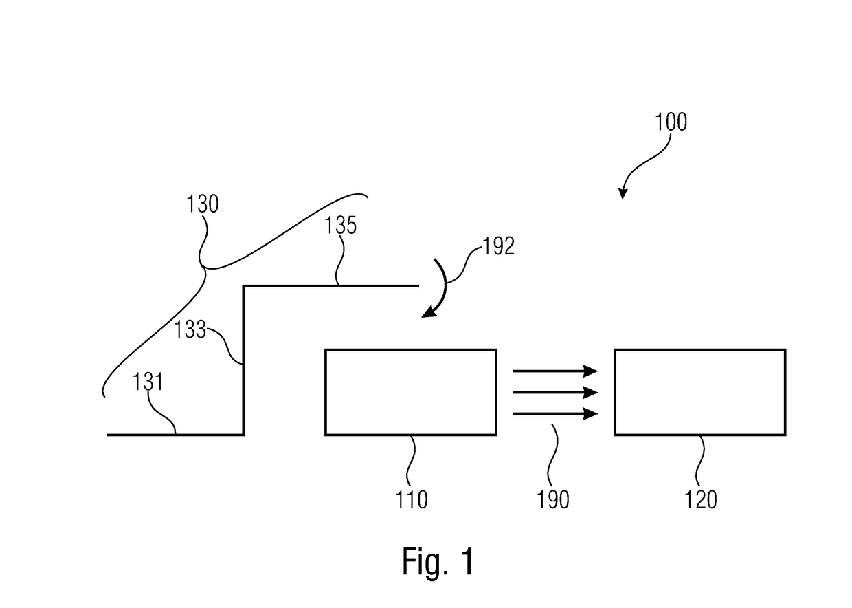
[0091]FIG. 1 shows a schematic sectional view of an electromechanical component 100 in accordance with a first embodiment of the present invention. The electromechanical component 100 includes a first electrode 110, a second electrode 120, and an elastically deformable proving structure 130. The first electrode 110 and the second electrode 120 are arranged to generate a useful electrical field in the event of there being a potential difference between the first electrode 110 and the second electrode 120. The proving structure 130 is configured to be deflected, for example by an electrostatic force, in the event of there being the potential difference between the first electrode 110 and the second electrode 120. The electromechanical component 100 is configured to have a useful effect, caused by the useful field, which differs from the deflection of the proving structure 130.

[0092]In other words, it may be said that by means of the above-described proving structure 130, a de...


PUM


Abstract

An electromechanical component and an electromechanical component arrangement for proving the existence of a potential difference which consists of a first electrode, a second electrode and a proving structure. The proving structure is configured to be deflected in the event of there being a potential difference. In addition, an electromechanical component is configured to generate a useful effect.A method implements operation of an electromechanical component for proving the existence of a potential difference, other methods implement operation for performing a functional test on the electromechanical component.

Description

CROSS-REFERENCE TO RELATED APPLICATIONS[0001]This application is a continuation of copending International Application No. PCT / EP2017 / 058669, filed Apr. 11, 2017, which is incorporated herein by reference in its entirety, and additionally claims priority from German Application No. 102016206208.5, filed Apr. 13, 2016, which is also incorporated herein by reference in its entirety.BACKGROUND OF THE INVENTION[0002]An embodiment of the present invention relates to an electromechanical component. A further embodiment relates to an electromechanical component arrangement. Further embodiments relate to operational procedures and methods of performing functional tests on the electromechanical component. An embodiment of the invention relates to a device for proving an electrical potential by means of a mechanically deflectable plate.[0003]In order to achieve further reduction in the size of integrated components, the technology used for manufacturing, for example lithography, needs to be c...

Claims


Application Information

Patent Timeline
IPC IPC(8): G01R15/16G01R35/00G01R29/12
CPCG01R15/165G01R35/00G01R29/12
Inventor ELSA ER, LINUSSCHULZE, MATTHIASFRIEDRICHS, MARTINHOHLE, CHRISTOPHKUNZE, DETLEF
Owner FRAUNHOFER GESELLSCHAFT ZUR FOERDERUNG DER ANGEWANDTEN FORSCHUNG EV
Why Eureka
Try Eureka