Vibratory sports equipment
A sports equipment and vibration-type technology, applied in passive exercise equipment, medical science, diagnosis, etc., can solve problems such as hidden safety hazards, lack of identification of specific user detection institutions, etc., to achieve the effect of reducing safety hazards
- Summary
- Abstract
- Description
- Claims
- Application Information
AI Technical Summary
Problems solved by technology
Method used
Image
Examples
Embodiment 1
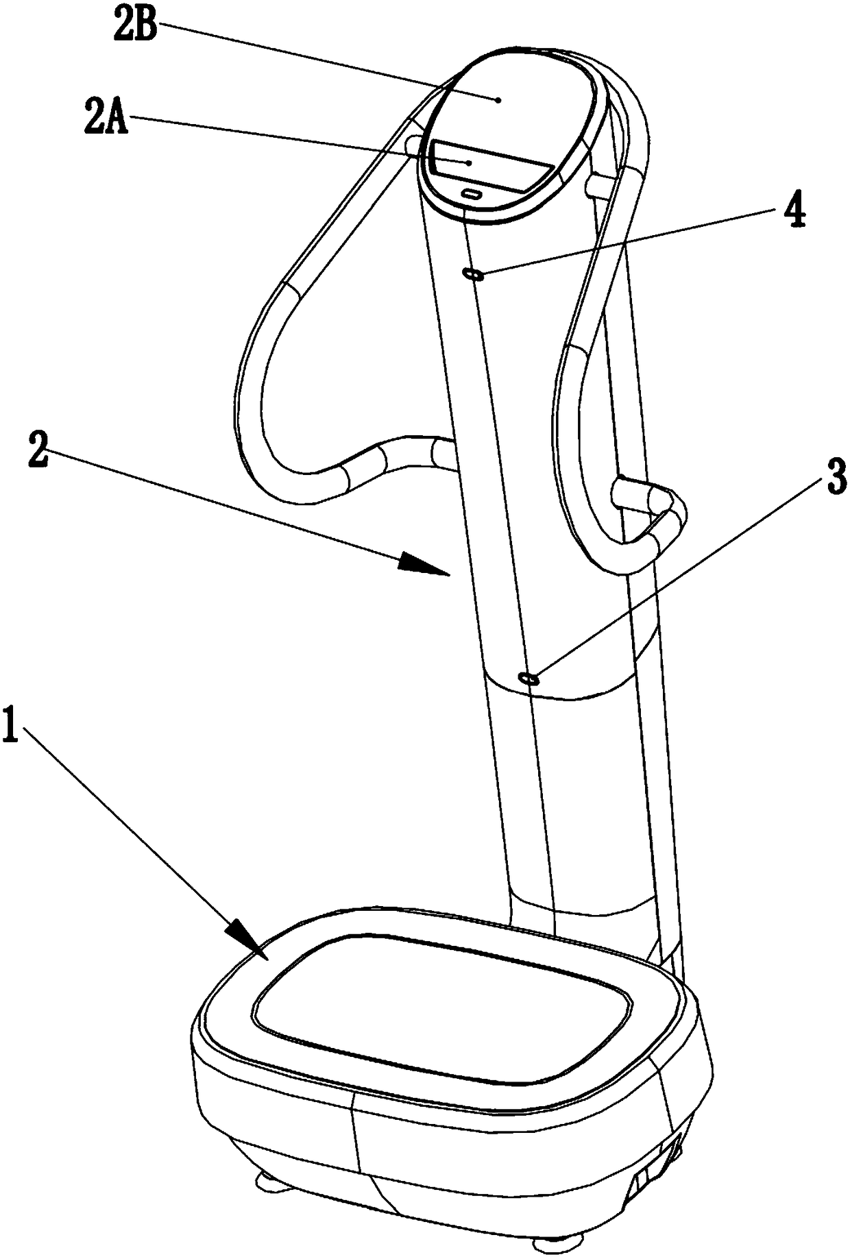
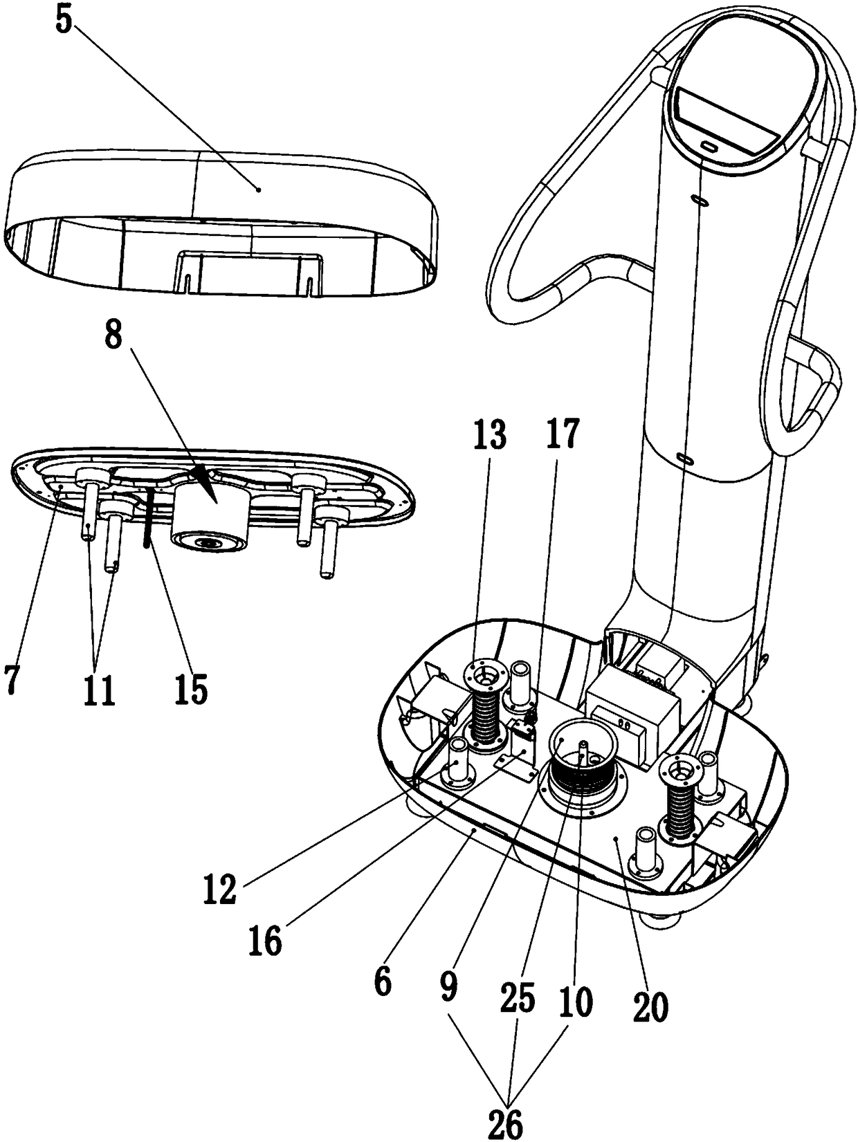
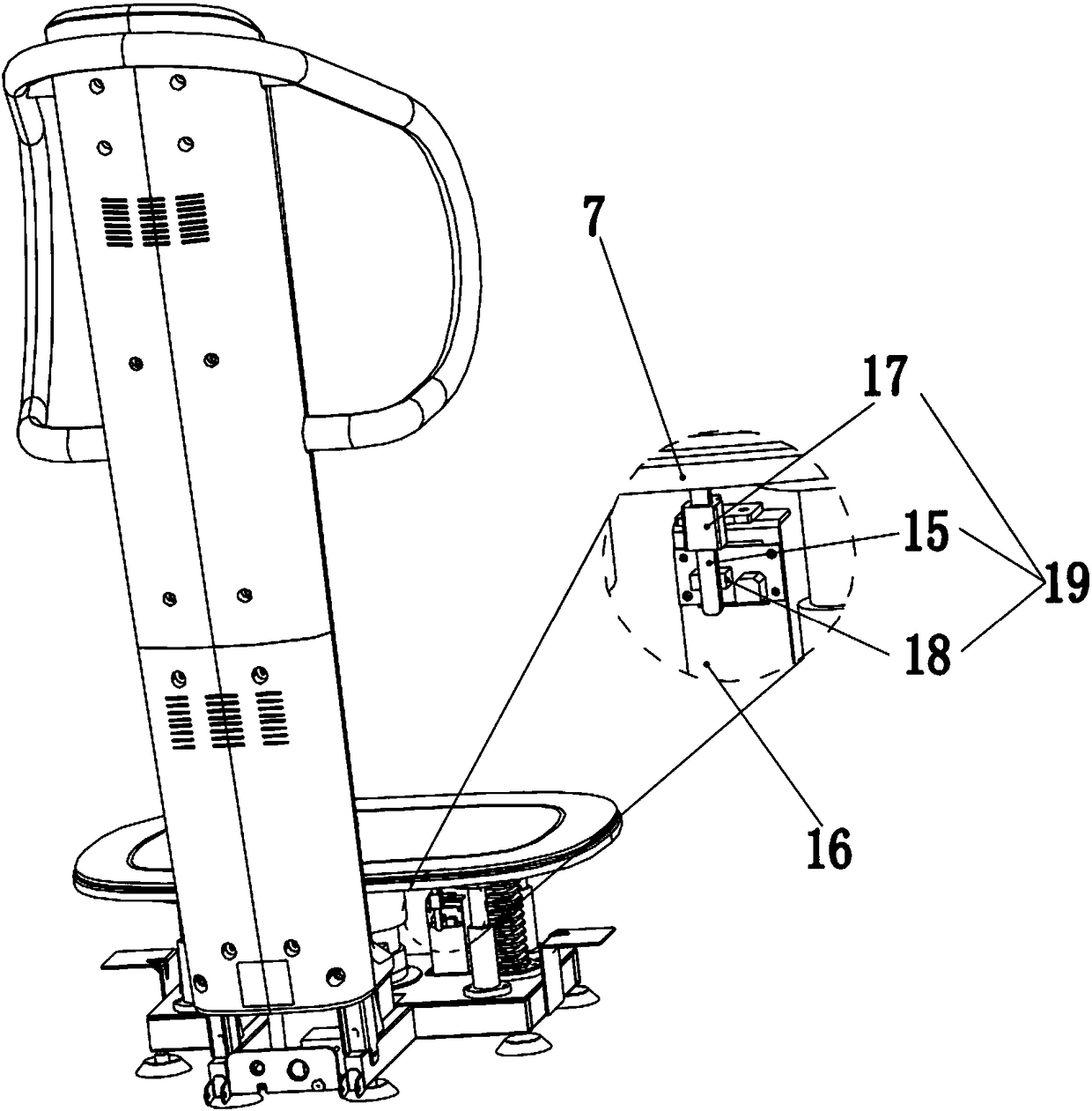
[0036] See Figure 1-Figure 11 As shown, a kind of vibrating sports equipment of the present invention has a base 20, a bearing seat 7 positioned above the base 20 for carrying the user, and a bearing seat 7 located between the base 20 and the bearing base 7 for driving the bearing base 7 relative to the base. The driving mechanism of seat 20 vibrations and the processing mechanism controlling the working state of the driving mechanism; the vibration-type sports equipment also includes a body weight detection mechanism for detecting user weight information, and the body weight detection mechanism is electrically connected to the processing mechanism so that the processing mechanism can The working state of the drive mechanism is controlled according to the user's weight information detected by the weight detection mechanism.
[0037] Please check figure 1 , the vibratory exercise equipment of the present invention includes a vibrating part 1 and an armrest part 2 for supporti...
Embodiment 2
[0046] See Figure 12-Figure 15 Shown, a kind of vibrating motion equipment of the present invention, its difference with embodiment 1 is:
[0047] The body weight detection mechanism is a load sensing device, including a plurality of load detection sensors 14 arranged on the base 20; each load detection sensor 14 is electrically connected to the processing mechanism.
[0048] In this embodiment, the bottom of the base is provided with several supporting feet 201 , the number of the load detection sensors 14 is consistent with the number of supporting feet 201 , and there is a one-to-one correspondence between the two. One end of each load detection sensor 14 is respectively locked on the corresponding support leg 201 , and the other end is abutted against the base 20 . Specifically, hardware 202 is fixed on the bottom of the base 20 close to each supporting foot 201, and the other end of the load detection sensor 14 is closely attached to the hardware 202, as Figure 14 sho...
PUM
 Abstract
Description
Claims
Application Information
 - R&D Engineer
- R&D Manager
- IP Professional
- Industry Leading Data Capabilities
- Powerful AI technology
- Patent DNA Extraction
Browse by: Latest US Patents, China's latest patents, Technical Efficacy Thesaurus, Application Domain, Technology Topic, Popular Technical Reports.
© 2024 PatSnap. All rights reserved.Legal|Privacy policy|Modern Slavery Act Transparency Statement|Sitemap|About US| Contact US: help@patsnap.com


