Low-temperature waste heat recovering device

A waste heat recovery and low temperature technology, which is applied in heat exchangers, heat transfer modification, heat exchange equipment, etc., can solve the problems of high maintenance cost, difficult recovery, and inability to recover and reuse waste heat, so as to improve the effect of waste heat recovery, Effect of improving heat exchange efficiency

Inactive Publication Date: 2018-09-11
宁波金名片能源科技有限公司
View PDF6 Cites 1 Cited by
  • Summary
  • Abstract
  • Description
  • Claims
  • Application Information

AI Technical Summary

Problems solved by technology

[0002] A large amount of waste hot water in bathing centers, hot springs, washing plants, printing and dyeing plants, etc., is usually discharged directly due to its low temperature, many impurities, and difficulty in recycling, which will not only cause a lot of energy waste, At the same time, it will also cause serious pollution to the environment
[0003] Traditional waste heat recovery heat exchangers mainly have two forms, namely plate heat exchangers and spiral plate heat exchangers; however, both plate heat exchangers and spiral plate heat exchangers are composed of layers The corrugated metal plates are stacked, and the heat exchange is completed during the reverse flow of cold water and hot water. In order to increase the heat exchange area and improve the heat exchange efficiency, the distance between the plates is small, which is easy to cause blockage and high maintenance costs; in addition, the driving force of heat exchange From the temperature difference between cold and hot water, the temperature of the above-mentioned wastewater is low, and the existing heat exchanger cannot recover and reuse the waste heat well; therefore, its structure needs to be further improved

Method used


Image

  • Low-temperature waste heat recovering device

Examples


Embodiment Construction

[0018] The present invention will be further described in detail below in conjunction with the accompanying drawings and embodiments.

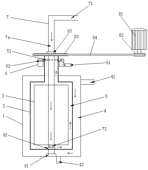
[0019] Such as figure 1 Shown is the structural representation of the present invention,

[0020] The reference signs therein are: outer cylinder 1, inner cylinder 2, rotating cylinder 3, waste hot water channel 4, waste hot water inlet 41, waste hot water outlet 42, warm water channel 5, warm water outlet hole 51, warm water collector 6 , warm water outlet 61, baffle plate 62, cold water pipe 7, cold water channel 7a, cold water inlet 71, cold water outlet hole 72, driving motor 81, driving wheel 82, driven wheel 83, transmission belt 84, lower bearing 91, waterproof bearing 92, upper bearing 93.

[0021] Such as figure 1 as shown,

[0022] A low-temperature waste heat recovery device, comprising an outer cylinder 1, an inner cylinder 2 is arranged inside the outer cylinder 1, and a rotating cylinder 3 is arranged between the inner cylind...


PUM


Abstract

The invention discloses a low-temperature waste heat recovering device. The low-temperature waste heat recovering device comprises an outer barrel; an inner barrel is arranged in the outer barrel; a rotating barrel is arranged between the inner barrel and the outer barrel and is connected with a rotating driving mechanism; a waste hot water channel is formed between the outer barrel and the rotating barrel; a waste hot water inlet is formed in the upper part of the outer barrel; a waste hot water outlet is formed in the lower part of the outer barrel; a warm water channel is formed between therotating barrel and the inner barrel; warm water discharge holes are formed in the upper part of the rotating barrel; a warm water collector is arranged outside the warm water discharge holes; a warmwater outlet is formed in the warm water collector; a cold water pipe is vertically arranged on the inner barrel; the upper part of the cold water pipe penetrates out of the rotating barrel; a cold water channel is formed in the cold water pipe; a cold water inlet is formed in the upper end of the cold water pipe; and cold water discharge holes are formed in the lower part of the cold water pipeand communicate with the warm water channel. The low-temperature waste heat recovering device has the advantages of simple structure, convenience in fabrication, and high heat exchange efficiency.

Description

technical field [0001] The invention relates to the technical field of waste heat recovery, in particular to a low-temperature waste heat recovery device. Background technique [0002] A large amount of waste hot water in bathing centers, hot springs, washing plants, printing and dyeing plants, etc., is usually discharged directly due to its low temperature, many impurities, and difficulty in recycling, which will not only cause a lot of energy waste, At the same time, it will cause serious pollution to the environment. [0003] Traditional waste heat recovery heat exchangers mainly have two forms, namely plate heat exchangers and spiral plate heat exchangers; however, both plate heat exchangers and spiral plate heat exchangers are composed of layers The corrugated metal plates are stacked, and the heat exchange is completed during the reverse flow of cold water and hot water. In order to increase the heat exchange area and improve the heat exchange efficiency, the distance...

Claims


Application Information

Patent Timeline
Patent Type & Authority Applications(China)
IPC IPC(8): F28D21/00F28F13/12
CPCF28D21/0012F28F13/125
Inventor 唐一波
Owner 宁波金名片能源科技有限公司
Why Eureka
Try Eureka