
Self inflation pneumatic tricycle and use method thereof

A tricycle, self-inflating technology, applied to bicycle accessories, bicycle brakes, tire measurement, etc., can solve the problems of pneumatic tricycle inflation troubles, etc., achieve good braking effect, increase inertia, and overcome resistance

Active Publication Date: 2018-09-11
ANHUI UNIVERSITY OF TECHNOLOGY AND SCIENCE
View PDF18 Cites 1 Cited by
  • Summary
  • Abstract
  • Description
  • Claims
  • Application Information

AI Technical Summary

Problems solved by technology

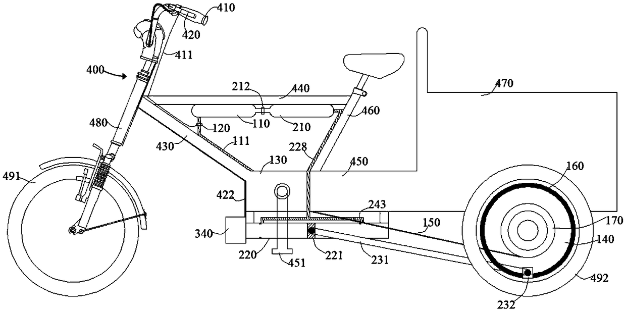
[0006] The purpose of the present invention is to solve the problem that the existing pneumatic tricycle is too cumbersome to inflate, and to provide a self-inflating pneumatic tricycle and its use method, through which the gas storage tank is connected in series with the energy supply gas tank, and the compression ratio of the compression ratio can be adjusted when braking. The cylinder compresses air into the air storage tank to inflate, and uses the kinetic energy during braking to complete self-inflation, which is more energy-saving and will not affect the normal use of the energy-supply air tank

Method used


Image

  • Self inflation pneumatic tricycle and use method thereof
  • Self inflation pneumatic tricycle and use method thereof
  • Self inflation pneumatic tricycle and use method thereof

Examples


Embodiment 1

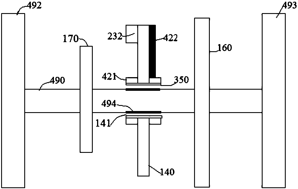
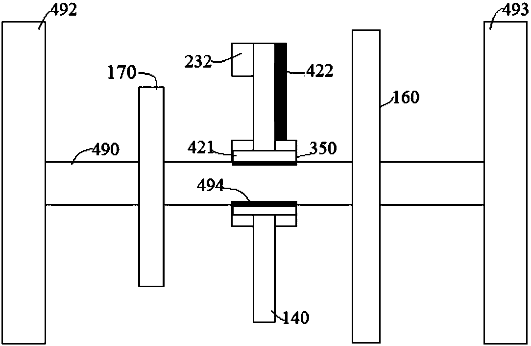
[0044] Refer to the attached figure 1 , figure 2 , image 3 and Figure 4 As shown, a self-inflating pneumatic tricycle in this embodiment includes a booster unit 100, an inflatable unit 200, and a vehicle body 400. The vehicle body 400 includes a speed control lever 410, a braking mechanism 420, a pedal bracket 430, and a lateral frame. 440, pedals 450, seat support rod 460, carriage 470, front wheel bracket 480, drive shaft 490 and front wheel 491 on which gear 494, first rear wheel 492, second rear wheel 493 and Flywheel 160, the flywheel 160 can store part of the energy of the power wheel 170 to overcome the resistance of other strokes, so that the power wheel 170 rotates evenly, and the flywheel 160 increases the inertia of the power wheel 170, so that the power wheel 170 can easily The gear 494 is matched with the brake actuator end 421 of the brake mechanism 420 , and the brake mechanism 420 controls the brake actuator end 421 to contact the gear 494 . The speed re...

Embodiment 2

[0055] A method of using a pneumatic tricycle of the present embodiment, the specific steps of the method are:

[0056] Step one, help

[0057] The compressed gas in the air storage tank 210 is sent to the booster unit 100, and the booster unit 100 is used to output pneumatic booster for the power wheel 170;

[0058] Step 2. Self-inflating

[0059] When the brake mechanism 420 is pressed for braking, the booster unit 100 stops outputting power, and the inflatable unit 200 starts to recover the power. The compression cylinder 220 of the inflatable unit 200 compresses the gas, and the compressed gas is transported to the gas storage tank 210 through a pipeline for inflation.

[0060] The method of this embodiment utilizes the kinetic energy during braking to complete self-inflation, which is more energy-saving.


PUM


Abstract

The invention relates to a self inflation pneumatic tricycle and a use method thereof, and belongs to the field of a pneumatic tricycle. The self inflation pneumatic tricycle comprises a power assistance unit, an inflation unit and a tricycle body, wherein the inflation unit comprises a gas storage tank and a compression cylinder; the tricycle body comprises a speed regulating rod, a brake mechanism and a transmission shaft; the speed regulating rod is used for regulating the gas supply quantity of an energy supply gas tank; the brake mechanism is used for regulating the work efficiency of thecompression cylinder; the brake execution end of the brake mechanism is matched with the transmission shaft; the brake execution end is close to the transmission shaft and is fixed with the transmission shaft. At the moment, the inflation unit works; the gas storage tank is used for storing air compressed by the compression cylinder; the compression cylinder is connected with the gas storage tankthrough a pipeline; the compressed gas is conveyed into the gas storage tank through a pipeline; inflation is performed; the kinetic energy during braking is used for completing the self inflation; more energy can be saved.

Description

technical field [0001] The invention belongs to the field of pneumatic tricycles, in particular to a self-inflating pneumatic tricycle and a use method thereof. Background technique [0002] Moped is a kind of light transportation between tricycles and light motorcycles. It occupies a place in the highly competitive transportation industry with its own advantages of being light, small and cheap. At present, there are generally two types of general-purpose mopeds on the market, namely, fuel-engine mopeds and electric mopeds. The two types of mopeds have their own advantages. The fuel moped uses a two-stroke engine due to its simple structure, resulting in insufficient fuel combustion and the release of a large amount of pollutants such as CO and tiny carbon particles, which cannot fundamentally solve the pollution problem. The energy consumption of electric mopeds does not come directly from fossil fuels, but from the electricity charged into the battery. In addition, the en...

Claims


Application Information

Patent Timeline
Patent Type & Authority Applications(China)
IPC IPC(8): B60C23/00B62L3/02B62L1/00B62M6/00B62M1/10B62M19/00
CPCB62L1/005B62L3/023B62M1/10B62M6/00B62M19/00B60C23/003B60C23/005
Inventor 徐振法王银凤梁利东谢正好
Owner ANHUI UNIVERSITY OF TECHNOLOGY AND SCIENCE
Learn More