
Fast-changing manipulator

A manipulator and blind hole technology, applied in the field of manipulators, can solve the problems of low economy, unsuitable for quick assembly and disassembly, complex manipulator structure, etc., and achieve high efficiency.

Inactive Publication Date: 2018-09-11
王华银
View PDF5 Cites 9 Cited by
  • Summary
  • Abstract
  • Description
  • Claims
  • Application Information

AI Technical Summary

Problems solved by technology

[0002] Manipulators are widely used and are high-tech products in industrial manufacturing. They are used to replace manual repetitive labor. In use, frequent assembly and disassembly of manipulators is often encountered. Most of the current manipulators are based on traditional couplings, pin connections, Key connection and other methods are not suitable for frequent quick assembly and disassembly, which makes the work efficiency low, and the existing manipulators are often complex in structure, suitable for various high-precision grasping, but there are still many simple general-purpose grasping in existing applications. The existing high-precision manipulators are not applicable and the economy is low

Method used


Image

  • Fast-changing manipulator
  • Fast-changing manipulator
  • Fast-changing manipulator

Examples


Embodiment Construction

[0022] The implementation of the present invention will be illustrated by specific specific examples below, and those skilled in the art can easily understand other advantages and effects of the present invention from the contents disclosed in this specification.

[0023] Below in conjunction with accompanying drawing and embodiment the present invention will be further described:

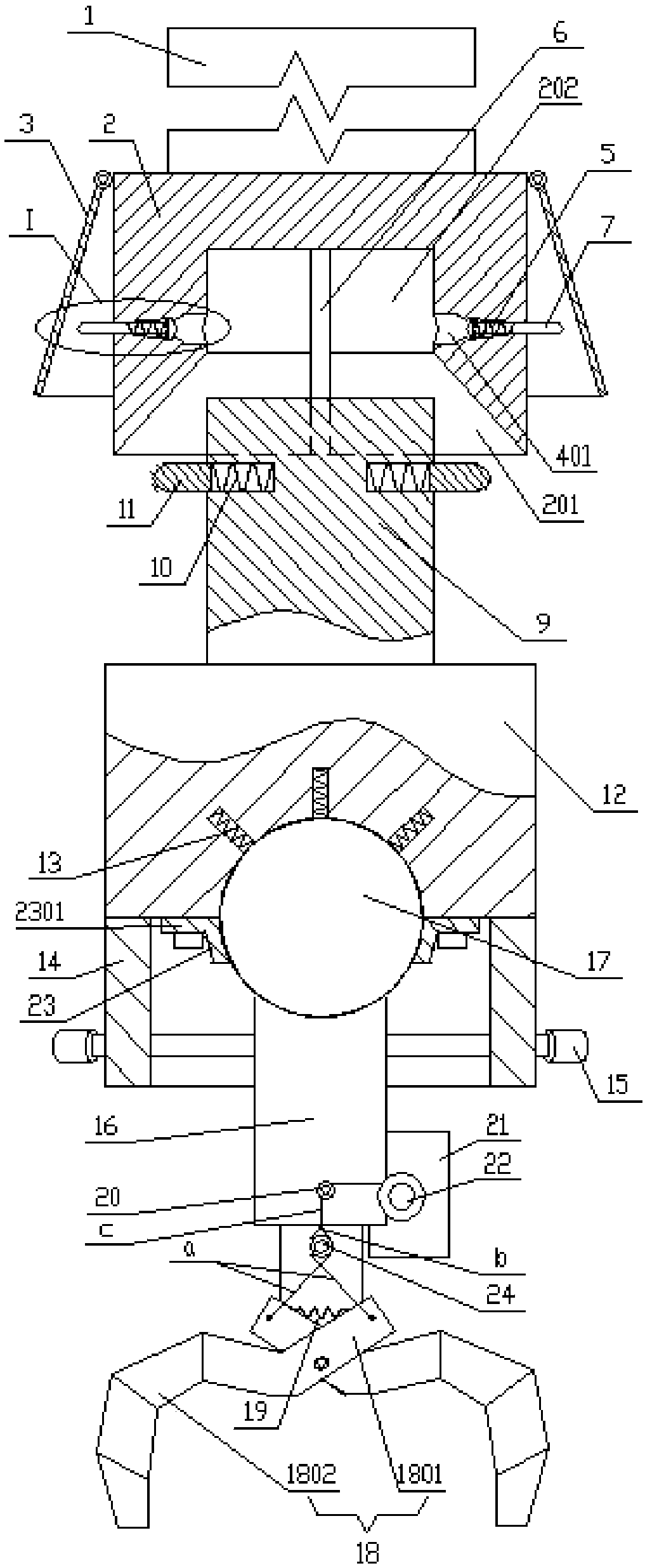
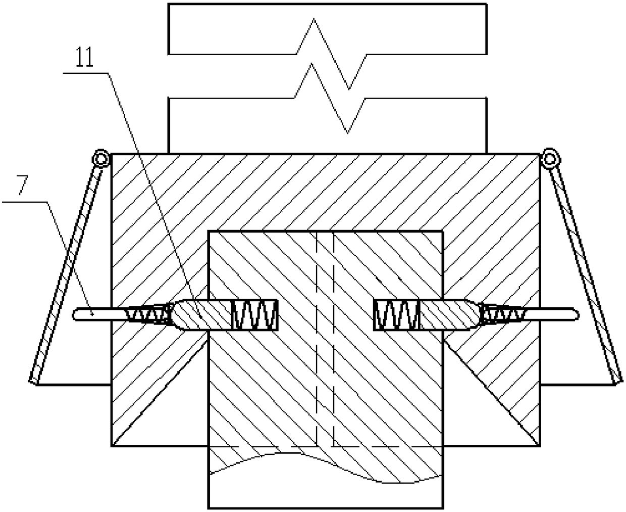
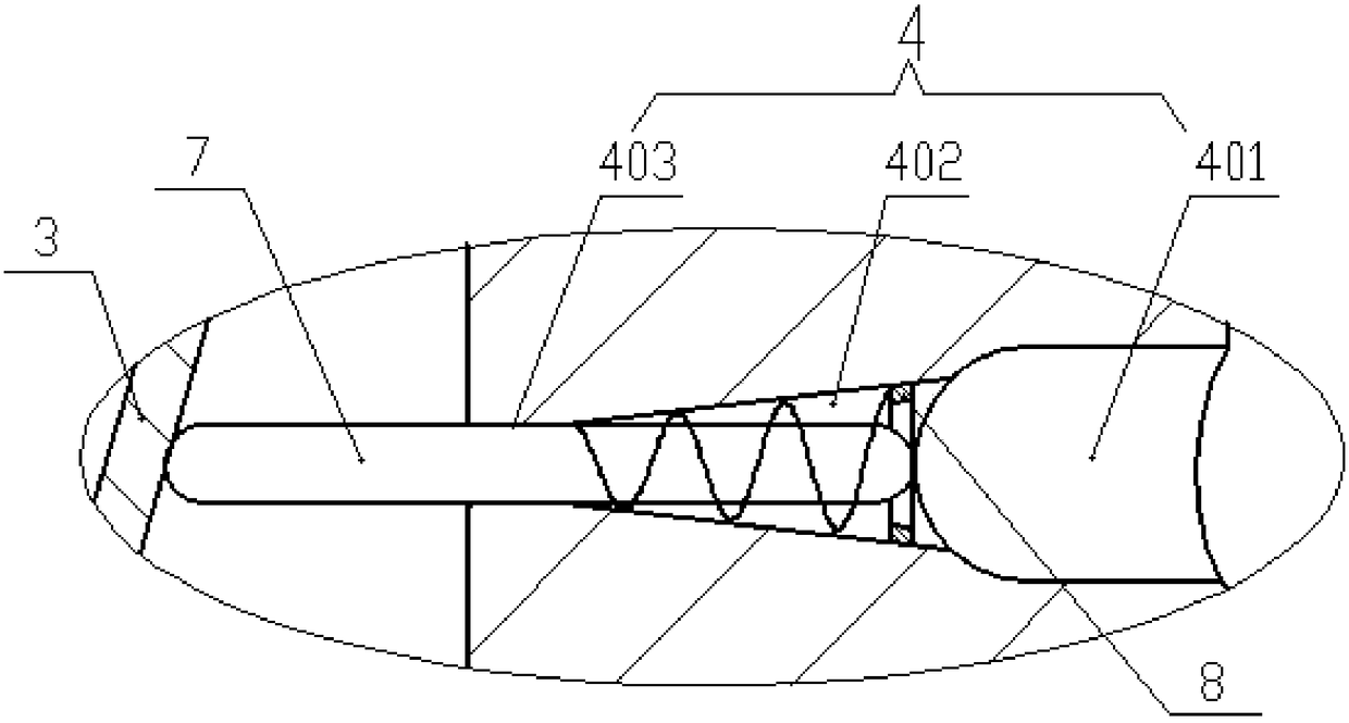
[0024] Such as figure 1 As shown in -3, a quick-change manipulator includes an optical axis 1, a socket part, and a ferrule part from top to bottom; the ferrule part is detachably inserted into the socket part. The socket part includes a cylindrical body 2 , an arc handle 3 , a pin 7 and a conical spring 5 . The top of the body 2 is coaxially connected to the optical axis 1, and the bottom is provided with a blind hole, and the blind hole includes a conical hole 201 and a cylindrical hole 202 connected on the body 2 from the outside to the inside, and the conical hole 201 The large end is located...


PUM


Abstract

The invention discloses a fast-changing manipulator. A plugging core part is detachably inserted into a socket part; the socket part comprises a body, an arc holding piece, a cylinder pin and a cone spring; a blind hole is formed in the body and sequentially comprises a cone hole and a cylinder hole from outside to inside, and the cone hole coaxially communicates with the cylinder hole; a protruding edge used for positioning is further arranged on the side wall of the blind hole; the plug core part comprises a cylindrical mandrel; and a cylinder spring is connected in a cylinder blind hole ofthe mandrel. A paw part comprises a connection part and a grabbing mechanism; a smooth ball is fixed to the top end of a connection rod, and two fingers used for grabbing goods are hinged to the bottom end; the ball is connected with a tension spring, and is closely attached to the groove wall of a groove under the effects of the tension spring; a reset spring is arranged between two straight handle portions of the two fingers; the free ends of the two straight handle portions are each connected with a steel wire; and the two steel wires are wound around a first pulley, and then are connectedwith a wheel disk driven by a micro motor. The fast-changing manipulator is simple and compact in structure, can achieve fast assembling and disassembling and greatly improves the work efficiency.

Description

technical field [0001] The invention belongs to the technical field of manipulators, in particular to a manipulator that can be replaced quickly. Background technique [0002] Manipulators are widely used and are high-tech products in industrial manufacturing. They are used to replace manual repetitive labor. In use, frequent assembly and disassembly of manipulators is often encountered. Most of the current manipulators are based on traditional couplings, pin connections, Key connection and other methods are not suitable for frequent quick assembly and disassembly, which makes the work efficiency low, and the existing manipulators are often complex in structure, suitable for various high-precision grasping, but there are still many simple general-purpose grasping in existing applications. However, the existing high-precision manipulators are not suitable for taking functions, and the economy is low. For example, in actual production, manipulators are often used to grab ligh...

Claims


Application Information

Patent Timeline
Patent Type & Authority Applications(China)
IPC IPC(8): B25J15/04
CPCB25J15/0408
Inventor 王华银
Owner 王华银
Learn More