Eureka AIR delivers breakthrough ideas for toughest innovation challenges, trusted by R&D personnel around the world.

Vertical connection structure of photovoltaic module and photovoltaic module thereof

A vertical connection structure and photovoltaic module technology, applied in photovoltaic power generation, photovoltaic modules, electrical components, etc., can solve the problems of waste, easy dust accumulation, burrs and protrusions, etc., achieve easy assembly and fastening, and improve connection tightness , the effect of a good protective structure

Pending Publication Date: 2018-09-07
PERLIGHT SOLAR
View PDF6 Cites 2 Cited by
  • Summary
  • Abstract
  • Description
  • Claims
  • Application Information

AI Technical Summary

Problems solved by technology

[0002] Photovoltaic modules need to protect and connect their frames through profiles. At present, in the frame of traditional crystalline silicon solar modules, the adjacent aluminum materials are cut into 45° angles for butt joint. May have burrs even after sanding
The grinding process also increases the waste of human resources, and there may still be burrs and protrusions after grinding, especially some aluminum materials with black anti-corrosion coating on the surface will reveal the silver-white internal structure after grinding, which is harmful to appearance and anti-corrosion. unfavorable
At the same time, conventional profiles are easy to accumulate dust near the edge banding area. After a long time, they will block the cells and make the local light transmittance low.

Method used


Image

  • Vertical connection structure of photovoltaic module and photovoltaic module thereof
  • Vertical connection structure of photovoltaic module and photovoltaic module thereof
  • Vertical connection structure of photovoltaic module and photovoltaic module thereof

Examples


Embodiment Construction

[0036] Below in conjunction with specific embodiment, content of the present invention is described in further detail:

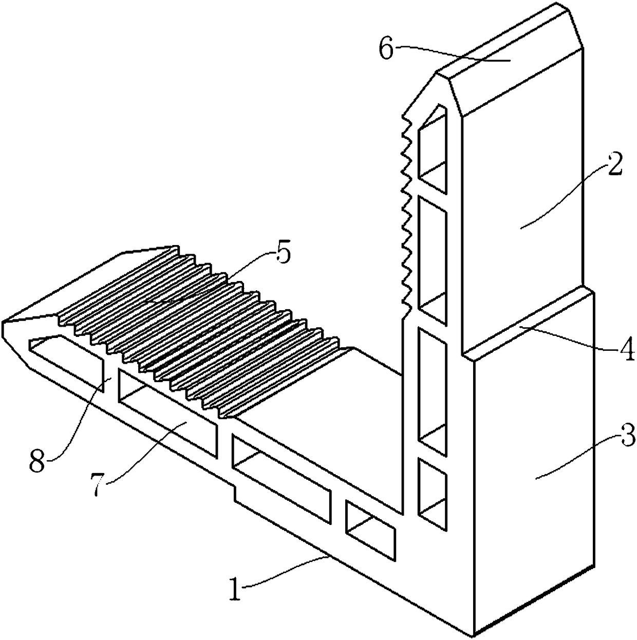
[0037] In order to achieve the purpose of the present invention, a vertical connection structure of a photovoltaic module includes: a corner code 1 with a connecting arm, a sawtooth surface 5, and a seam surface 4; Along the length direction, it is divided into an insertion section 3 and a connecting section 2; the serration surface 5 is located on the insertion section 3, and the serrations on the serration surface 5 have a steep slope surface and a gentle slope surface, and the steep slope surface faces the direction of the connection section 2; the mouth surface 4, Located at the junction of the insertion section 3 and the connection section 2, the seam surface 4 is perpendicular to the length direction of the insertion section 3 and the connection section 2; The end contacts; the corner protector has an L-shaped groove 13 in the length direction, and the...


PUM


Abstract

The invention discloses a vertical connection structure of a photovoltaic module and a photovoltaic module thereof. The vertical connection structure comprises a corner, which is provided with connecting arms, sawtooth surfaces and stop surfaces; the two connecting arms are vertically connected in an L shape, and each connecting arm is divided into an insertion section and a connection section along the length direction; the sawtooth surfaces are located on the insertion sections; the stop surfaces are located at the boundaries of the insertion sections and the connection sections, and are perpendicular to the length directions of the insertion sections and the connection sections; the insertion sections are in contact connection with the inner cavity of a profile, and the stop surfaces are in contact with the ends of the profile; and the corner guard is provided with a groove having an L-shaped length, the groove is in contact with the inner sides of the connection sections, and whenthe corner guard is assembled with the corner, the cross-sectional contours of the corner guard at the groove and the corner are the same as the cross-sectional contour of the profile. The corner clamps the periphery of the corner guard, the profile clamps the two ends of the corner guard, and the three are fixed tightly, so that the sharpness of the corner of the profile is eliminated, the repairof the profile is avoided and the assembly work of the personnel is reduced.

Description

technical field [0001] The invention relates to the field of photovoltaic module accessories, in particular to a vertical connection structure of a photovoltaic module and the photovoltaic module. Background technique [0002] Photovoltaic modules need to protect and connect their frames through profiles. At present, in the frame of traditional crystalline silicon solar modules, the adjacent aluminum materials are cut into 45° angles for butt joint. There may be burrs even after sanding. The grinding process also increases the waste of human resources, and there may still be burrs and protrusions after grinding, especially some aluminum materials with black anti-corrosion coating on the surface will reveal the silver-white internal structure after grinding, which is harmful to appearance and anti-corrosion. unfavorable. At the same time, conventional profiles are easy to accumulate dust near the edge banding area. After a long time, they will block the cells, resulting in ...

Claims


Application Information

Patent Timeline
IPC IPC(8): H02S30/10
CPCH02S30/10Y02E10/50
Inventor 董波李冲金叶
Owner PERLIGHT SOLAR
Why Eureka
Eureka Blog
Learn More