Gradient reflection type light guiding lamp box

A light box and gradient technology, applied in the field of gradient reflection light guide light boxes, can solve the problems of waste of manpower and material resources, inability to make ultra-thin light boxes, and high requirements for light box thickness

Pending Publication Date: 2018-09-07
SHANGHAI EDGE LIGHT IND
View PDF0 Cites 0 Cited by
  • Summary
  • Abstract
  • Description
  • Claims
  • Application Information

AI Technical Summary

Problems solved by technology

[0003] The disadvantage of the above-mentioned first type of light guide plate light box is: the LED is placed on the side of the light guide plate, and when the light of the LED enters the light guide plate, part of the light is irradiated outside the light guide plate. As the size increases, the overall uniformity of the light guide plate The disadvantage of the second type of side light source light box is: due to the use of side light source light source, the overall thickness of the light box is required to be high, and it cannot be made into an ultra-thin light box. When the size is large, the uniformity in the middle will also appear The problem of reduction; the disadvantage of the third type is: because the LEDs are placed at the bottom of the light box, more LEDs are required to be arranged, and the overall power is very large, which will release more heat and use more power.
There is a light-shielding layer between the side of the light guide plate that is closer to the LED light source and the diffuser plate to prevent the light from the LED light source from refracting into the diffuser plate. The scheme will use a large number of LEDs, and the power of the light box will be very large, which cannot achieve the purpose of energy saving. This scheme is more cumbersome in assembly and will waste a lot of manpower and material resources
[0005] In another structure disclosed in the prior art, the light guide plate is arranged in the frame, and the side light source is arranged on the edge of the light guide plate or buried inside the edge of the light guide plate. The light guide plate includes a plate body and light guide plates scattered on the plate body body; the light guide body includes a diamond-shaped cone base and a cone top, with a first inverted V edge and a second inverted V edge perpendicular to each other, the first inverted V edge is parallel to the incident direction of light, and the second inverted V edge is vertical Light incident direction, although this solution can improve the uniformity of the light box, but a large part of the light from the LED does not enter the light guide plate, and the overall brightness of the light box is low

Method used


Image

  • Gradient reflection type light guiding lamp box
  • Gradient reflection type light guiding lamp box
  • Gradient reflection type light guiding lamp box

Examples


Embodiment 1

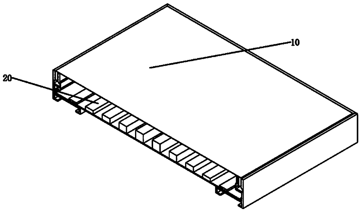
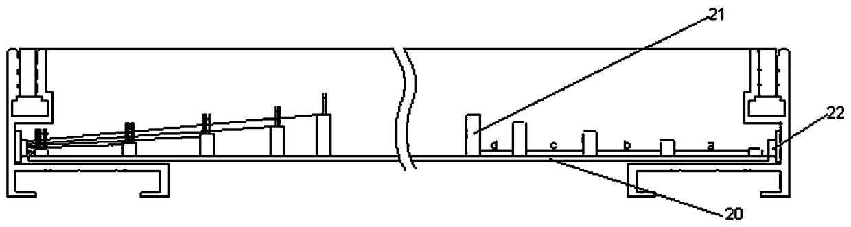
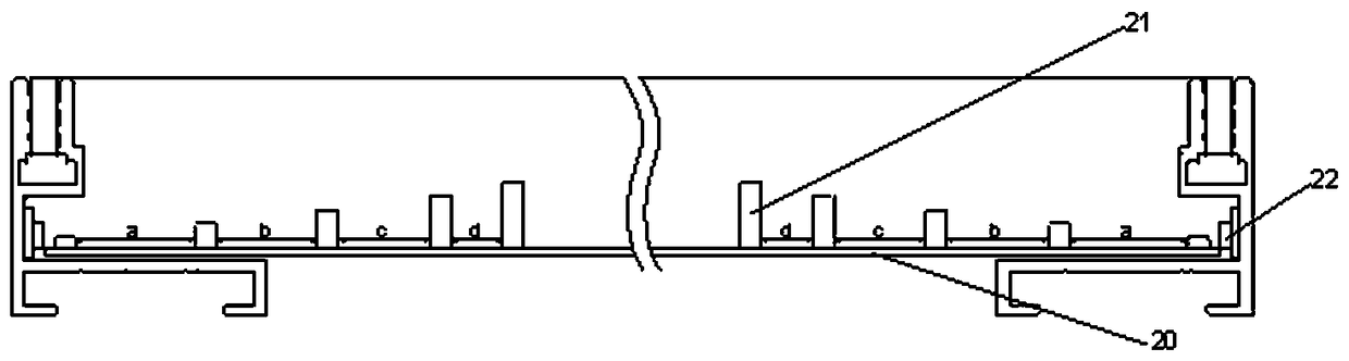
[0028] The gradient reflective light guide light box of the present invention comprises a light box body 10, a plurality of reflective panels 20 are arranged in the light box box 10, black reflectors 21 arranged in gradients are arranged on the reflective panel 20, and on both sides of the reflective panel 21 An LED light source 22 is provided on the side.

[0029] In the present invention, the black reflector 21 is from near to far away from the LED light source 22, and the size of the black reflector 21 is from small to large; From low to high; the distance between the black reflectors 21 is from near to far from the LED light source 22, and the distance between the black reflectors 21 is a>b>c>d.

[0030] In the present invention, the black reflector 21 is printed on the reflective panel 20; the shape of the black reflector 21 is a rectangle.

Embodiment 2

[0032] The gradient reflective light guide light box of the present invention comprises a light box body 10, a plurality of reflective panels 20 are arranged in the light box box 10, black reflectors 21 arranged in gradients are arranged on the reflective panel 20, and on both sides of the reflective panel 21 An LED light source 22 is provided on the side.

[0033] In the present invention, the black reflector 21 is from near to far away from the LED light source 22, and the size of the black reflector 21 is from small to large; From low to high; the distance between the black reflectors 21 is from near to far from the LED light source 22, and the distance between the black reflectors 21 is a>b>c>d.

[0034] In the present invention, the black reflector 21 is printed on the reflective panel 20; the shape of the black reflector 21 is cylindrical.

Embodiment 3

[0036] The gradient reflective light guide light box of the present invention comprises a light box body 10, a plurality of reflective panels 20 are arranged in the light box box 10, black reflectors 21 arranged in gradients are arranged on the reflective panel 20, and on both sides of the reflective panel 21 An LED light source 22 is provided on the side.

[0037] In the present invention, the black reflector 21 is from near to far away from the LED light source 22, and the size of the black reflector 21 is from small to large; From low to high; the distance between the black reflectors 21 is from near to far from the LED light source 22, and the distance between the black reflectors 21 is a>b>c>d.

[0038] In the present invention, the black reflector 21 is printed on the reflective panel 20; the shape of the black reflector 21 is a triangle.


PUM


Abstract

The invention aims at disclosing a gradient reflection type light guiding lamp box. The gradient reflection type light guiding lamp box comprises a lamp box body, wherein a plurality of reflection panels are arranged on the back surface of the lamp box body, black reflection bodies arrayed in a gradient manner are arranged on the reflection panels, and LED light sources are arranged on two sides of the reflection panels. Compared with the prior art, the gradient reflection type light guiding lamp box has the advantages that the reflection panels are arranged in the lamp box body, and the blackreflection bodies arrayed in a gradient manner are arranged on the reflection panels, so that the uniformity of the lamp box is high, the integral brightness of the lamp box is increased, the situations that relative more heat is released and relatively more electric energy is used are avoided, the gradient reflection type light guiding lamp box can meet the requirements of LED lamp boxes, and the purpose of the invention is achieved.

Description

technical field [0001] The invention relates to a gradient reflection light guide light box, in particular to a gradient reflection light guide light box. Background technique [0002] At present, LED light boxes mainly have three light source structures: the first one is to place LEDs on the side of the light guide plate, and then design some dots or grids on the light guide plate. Refraction, projecting out of the light guide plate to form a uniform surface light source; the second is to use LED side light source in the light box, design the LED side light source on the side wall of the light box, and change the light-emitting angle of the LED by adding a secondary optical lens to the LED , so that more light shines forward to form a uniform light; the third method uses a backlight as the light source of the light box, and places multiple rows of backlight at the bottom of the light box, and the light passes through the secondary refraction of the backlight lens to form a ...

Claims


Application Information

Patent Timeline
Patent Type & Authority Applications(China)
IPC IPC(8): G09F13/14
CPCG09F13/14G09F2013/142
Inventor 由磊尹起星李飞
Owner SHANGHAI EDGE LIGHT IND
Why Eureka
Try Eureka