
Tester capable of simulating track in braking state

A kind of rutting test and state technology, which is applied in the direction of material inspection products, etc., can solve the problems of not being able to meet the needs of one machine for multiple purposes, inconsistent road surface force conditions, inconsistent horizontal tangential force, etc. good effect

Pending Publication Date: 2018-09-07
CHANGSHA UNIVERSITY OF SCIENCE AND TECHNOLOGY +1
View PDF16 Cites 5 Cited by
  • Summary
  • Abstract
  • Description
  • Claims
  • Application Information

AI Technical Summary

Problems solved by technology

[0004] The main purpose of the existing rutting tester is to measure the high temperature stability, but there are still the following problems: 1) The test piece is mainly subjected to compressive stress during the test, and the corresponding deformation is mainly compaction deformation; 2) The test piece The force borne during the test is a fixed pressure, which is inconsistent with the alternating load that will occur in the actual process of the vehicle; 3) The horizontal tangential force generated by the rotation of the wheel is mainly caused by the friction between the tire and the road surface, which is different from the actual load. The horizontal tangential force generated by the vehicle during the braking process does not match; 4) The scope of application of the current test equipment is not enough, it cannot meet the multi-purpose of one machine, and the economy is not enough
[0006] The disadvantage of the above-mentioned patents is that the horizontal shear force generated during the test wheel rolling process during the test cannot simulate the horizontal shear force generated by the wheel when braking under actual conditions.
At the same time, the loading force of the equipment cannot realize variable load, which is inconsistent with the force on the road surface in the actual process.

Method used


Image

  • Tester capable of simulating track in braking state
  • Tester capable of simulating track in braking state
  • Tester capable of simulating track in braking state

Examples


Embodiment Construction

[0026] 1. The basic structure of the rutting tester under the simulated braking state

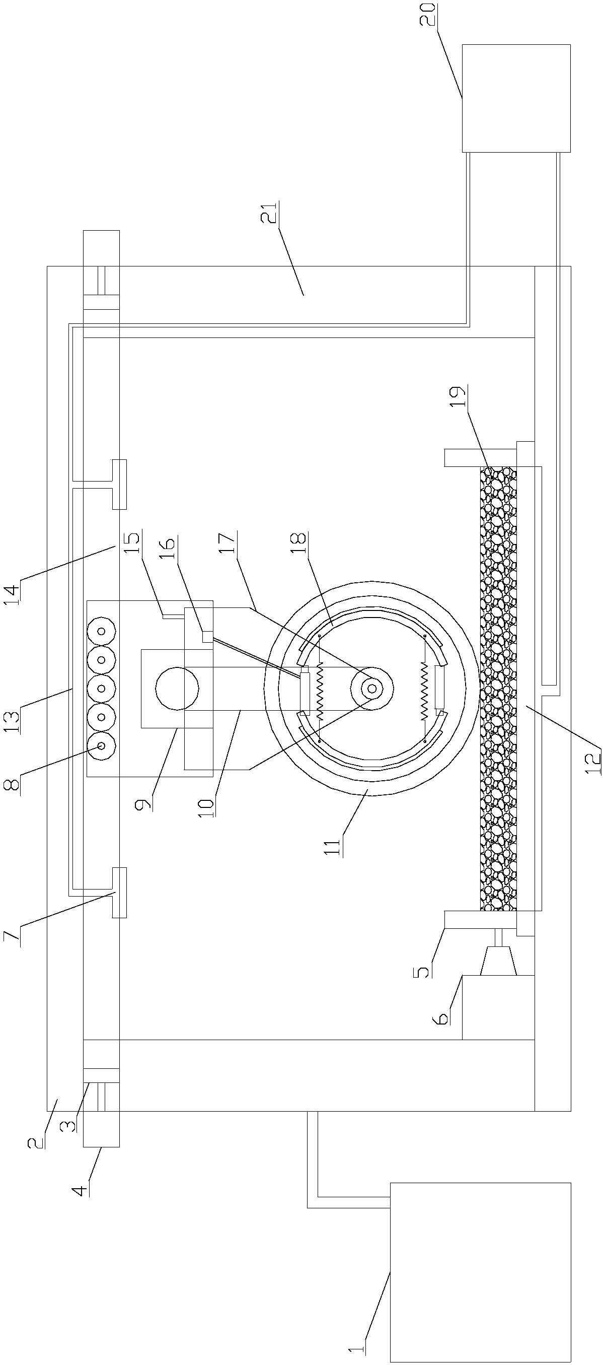
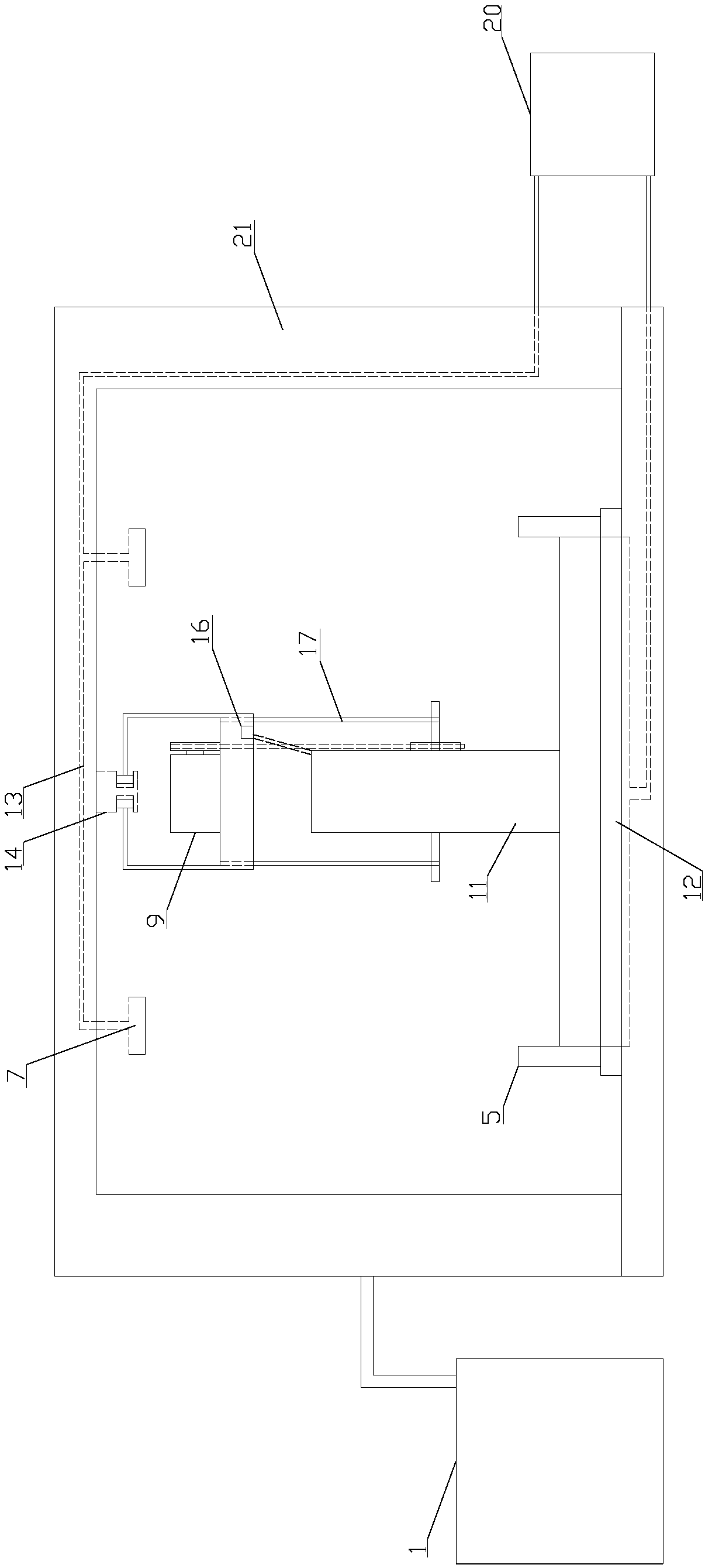
[0027] Such as figure 1 As shown, the rutting tester under the simulated braking state of the present invention includes a test main control measurement system transmitted by a data line; a bracket device; a drive device; a wheel set device; a pressure device; a simulated rainfall circulation device; a temperature control system.

[0028] The test main control measurement system 1 is located outside the test instrument, controlled by a computer, and uses sensors to transmit data to the test measurement system through data lines. The temperature control system is located inside the test chamber.

[0029] The support device includes a test stand 12 , a guide rail 14 and a wheel frame 17 . The test bench is located at the bottom of the instrument and consists of a hydraulic device, a test platform and a sliding push plate; the left sliding push plate is connected to the hydraulic device. Th...


PUM


Abstract

The invention discloses a tester capable of simulating a track in a braking state. The tester comprises a length-adjustable horizontal test bed, a test wheel provided with a braking system, a drivingmotor system, a guide driven wheel system, a guide cross beam capable of guiding the driving direction and adjusting the height through auxiliary motors, a precipitation cycle simulating system and atemperature control system. The tester is reasonable in structure design, compact in mounting, simple and easy to operate and good in use effect, can simulate the stress condition in the braking stateduring vehicle driving and can simulate the stress condition of a track plate under the variable load action, the actual problem that existing track instruments can only simulate stress of the trackplate in the vertical force state when crank connecting rods are used for driving test wheels to run can be effectively solved, a reliable tool is provided for detection of high-temperature performance of bituminous mixture test pieces and can be used as a tool for indoor scientific research.

Description

technical field [0001] The invention belongs to the technical field of road engineering test equipment, and in particular relates to a high-temperature stability test equipment for asphalt mixture. Background technique [0002] Rutting is a common form of pavement failure in which the asphalt mixture undergoes plastic flow deformation due to traffic load or continuous load under high temperature conditions, which eventually leads to the destruction and instability of the skeleton structure. The rutting test is a simple method to evaluate the high-temperature stability of asphalt mixture. At present, the rutting test has been included in the existing codes in my country. Its advantages are: the applied load mode reflects the actual stress on the road surface, and the instrument is relatively cheap. Easy to operate. However, there are still deficiencies in the existing rutting instrument, and there are many aspects of the instrument that can be improved. [0003] The formatio...

Claims


Application Information

Patent Timeline
IPC IPC(8): G01N33/42
CPCG01N33/42
Inventor 付其林张青江陈敬博魏建国张红日李平窦哲
Owner CHANGSHA UNIVERSITY OF SCIENCE AND TECHNOLOGY
Learn More