
Optical system and lamp employing same

An optical system and light source technology, which is applied in the light guide, optics, and lighting applications of the lighting system, can solve the problems of cross-lighting, affecting the projection effect, and the inability to achieve sufficient mixing of light beams, so as to avoid cross-lighting, prevent cross-lighting, The effect of reducing volume

Active Publication Date: 2018-09-07
GUANGZHOU HAOYANG ELECTRONICS CO LTD
View PDF8 Cites 8 Cited by
  • Summary
  • Abstract
  • Description
  • Claims
  • Application Information

AI Technical Summary

Problems solved by technology

Although this method can achieve a certain uniform light effect, whether the light source is fully mixed depends more on the light guide surface of the light guide or the light source itself. Only by changing the cross-sectional shape of the light guide or just making each A light guide rotated at a certain angle cannot achieve sufficient mixing of the beam, and the beams of multiple light guides pass through the corresponding lens to produce cross-light, which affects the projection effect

Method used


Image

  • Optical system and lamp employing same
  • Optical system and lamp employing same
  • Optical system and lamp employing same

Examples


Embodiment 1

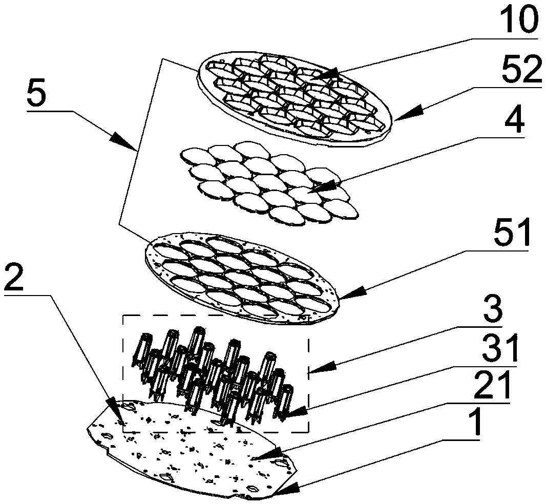
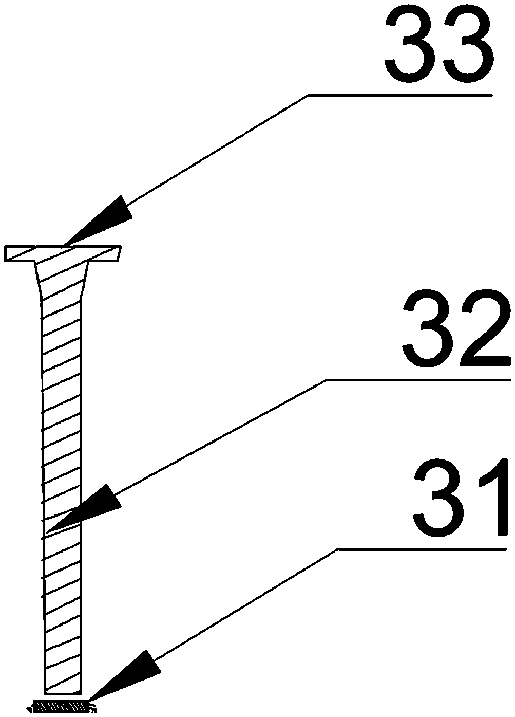
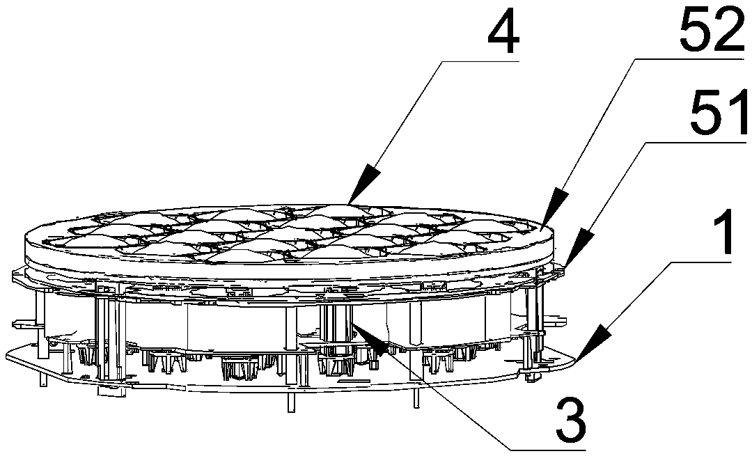
[0105] an optical system such as Figure 1~2 As shown, the optical system includes a substrate 1, a light source 2, a light guide 3 and a lens 4, the light source 2 is installed on the substrate 1, the light source 2 includes multiple groups of light emitting arrays 21, and each group of light emitting arrays 21 Correspondingly, a light guide body 3 is provided, and the light guide body 3 includes an incident surface 31, a light guide surface 32, and an output surface 33. The light emitted by the light emitting array 21 enters through the incident surface 31 of the light guide body 3, passes through the light guide The surface 32 is evenly lighted, and then output from the output surface 33, and the light from the light guide 3 is emitted through the lens 4 to form a beam. The optical system also includes a honeycomb cover 5, and the honeycomb cover 5 includes a plurality of through holes 10. The through hole 10 is set on the lens of the lens 4, the cross section of the throug...

Embodiment 2

[0143] Such as Figure 7 As shown, the difference between this embodiment and Embodiment 1 is that the deflection angle of the at least one group of light-emitting arrays relative to the other at least one group of light-emitting arrays is 180°.

Embodiment 3

[0145] Such as Figure 8 As shown, the difference between this embodiment and Embodiment 1 is that the deflection angle of the at least one group of light-emitting arrays relative to the other at least one group of light-emitting arrays is 270°.


PUM


Abstract

The invention provides an optical system and a lamp employing the same. The optical system comprises a substrate, light sources, light guide bodies and lenses, wherein the light sources are mounted onthe substrate and comprise a plurality of sets of light-emitting arrays; each set of light-emitting array corresponds to one of the light guide bodies; each light guide body comprises an incident face, a light guide face and an output face; light emitted by the light-emitting arrays enters through the incident faces of the light guide bodies, and is subjected to dodging by the light guide faces,and then output from the output faces; and light getting out of the light guide bodies passes through the lens to form a light beam to be emitted out. The optical system further comprises a honeycombcover with a plurality of through holes, wherein the through holes sleeve lens heads of the lens; the cross sections of the through holes are matched with the maximum cross sections of the lens headsof the lens; and the overall arrangement shape of the through holes on the honeycomb cover is matched with that of of the light sources on the substrate. By adoption of the technical scheme, optical crosstalk is effectively prevented while the uniformity of light spots is guaranteed.

Description

technical field [0001] The invention relates to an optical device, in particular to an optical system and a lighting fixture for mixing and uniforming light and having the function of preventing cross-lighting. Background technique [0002] Compared with fluorescent lamps, LED light sources have the advantages of small size, low power consumption, long life, and high luminous efficiency. They are a new generation of energy-saving and environmentally friendly light sources. At present, there are many fluorescent tubes made of LED light sources on the market to replace fluorescent tubes. Fluorescent tubes using LEDs as light sources have the advantages of fast response, high brightness, no flicker, no noise, long service life, and good versatility. They have been widely used in homes, offices, shopping malls, public places, and vehicles. widely used. [0003] In practical applications, light from multiple light sources is usually mixed, and the emission color of each light s...

Claims


Application Information

Patent Timeline
Patent Type & Authority Applications(China)
IPC IPC(8): F21K9/20F21V5/04F21V8/00F21V19/00F21Y115/10
CPCF21V5/04F21V19/001F21V2200/00F21K9/20F21Y2115/10F21V5/007F21V13/02F21W2131/406F21Y2105/18F21Y2113/13G02B3/0056G02B3/0075G02B19/0028G02B19/0066G02B27/0018G02B27/0994F21V9/40G02B6/0005G02B27/0961
Inventor 蒋伟楷其他发明人请求不公开姓名
Owner GUANGZHOU HAOYANG ELECTRONICS CO LTD
Learn More