
Cotton thread conveying device for textile

A technology of conveying device and cotton thread, which is applied in transportation and packaging, delivery of filamentous materials, thin material processing, etc. It can solve problems such as poor shock resistance, waste of manpower, and cotton thread is easy to break, so as to avoid excessive amplitude and increase shock resistance , the effect of preventing the cotton thread from slipping out

Inactive Publication Date: 2018-09-07
JIANGSU BEILIN TEXTILE CO LTD
View PDF0 Cites 6 Cited by
  • Summary
  • Abstract
  • Description
  • Claims
  • Application Information

AI Technical Summary

Problems solved by technology

[0002] With the continuous development of society, my country's textile industry has also made great progress. Various new types of textile equipment have emerged as the times require, greatly increasing the output and production efficiency of the textile industry. One of the textile cotton thread conveying devices uses It is more widely used, but there are many problems or defects in the existing textile cotton thread conveying device. First, the traditional textile cotton thread conveying device has poor shock resistance. When the amplitude is too large, the cotton thread is easy to break. Second, the traditional textile cotton thread conveying The device cannot take pictures of the conveying process. The traditional working method requires manual guarding, which wastes a lot of manpower. Third, the traditional textile cotton thread conveying device cannot remove the static electricity in the cotton thread, and the cotton thread is easily adsorbed together, which is difficult to take care of

Method used

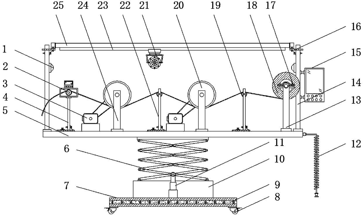
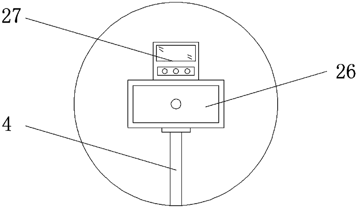
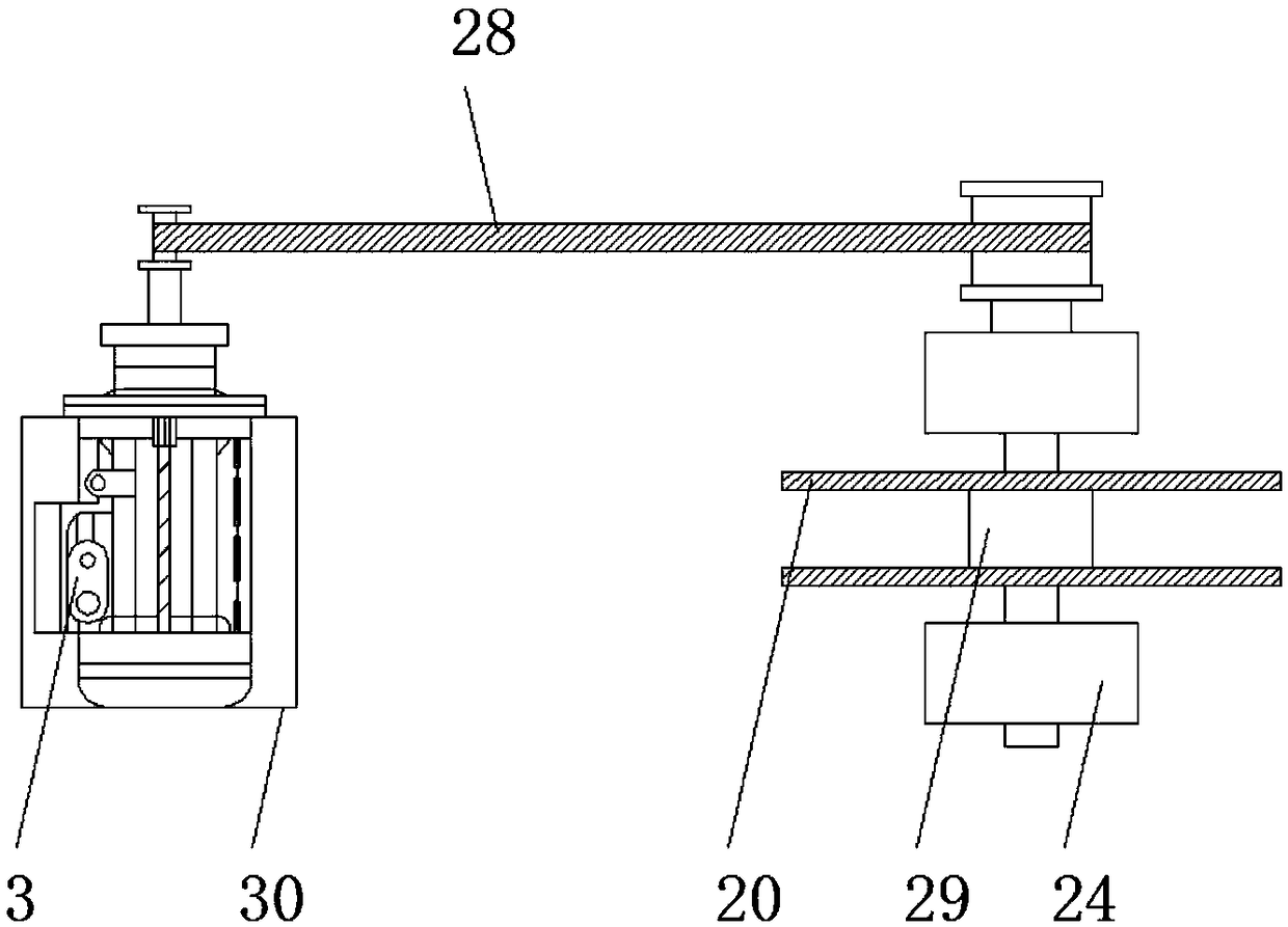

Image

  • Cotton thread conveying device for textile
  • Cotton thread conveying device for textile
  • Cotton thread conveying device for textile

Examples


Embodiment Construction

[0014] The following will clearly and completely describe the technical solutions in the embodiments of the present invention with reference to the accompanying drawings in the embodiments of the present invention. Obviously, the described embodiments are only some, not all, embodiments of the present invention. Based on the embodiments of the present invention, all other embodiments obtained by persons of ordinary skill in the art without making creative efforts belong to the protection scope of the present invention.

[0015] see Figure 1-3 , an embodiment provided by the present invention: a cotton thread conveying device for textiles, comprising an LED lamp 1, a base 7, a ground wire 12, a guide roller shaft 19 and a cross bar 25, and the four corners at the bottom of the base 7 are all Universal wheels 8 are installed, and brake pads are installed on the universal wheels 8 to increase the stability of the device when it stops. The inside of the base 7 is provided with a ...


PUM


Abstract

The invention discloses a cotton thread conveying device for textile. The cotton thread conveying device comprises LED lamps, a base, a ground wire, a guide roller shaft and a cross bar. Universal wheels are correspondingly installed at four corners of the bottom end of the base. A scissor frame support table is installed at the top end of the base. A scissor frame is installed at the top end of the scissor frame support table. Baffles are correspondingly installed at both ends of a conveying roller shaft. Guide wheel fixing columns are correspondingly installed at the portions at both ends ofthe top of a workbench and at the sides, close to wire roller support columns, of transmission roller shafts. Guide roller shafts are fixedly arranged between the top ends of the guide wheel fixing columns. The output end of a control panel is electrically connected with the input end of a motor through a wire. The output end of the control panel is electrically connected with the input end of acamera shooting device through a wire. The output end of the control panel is electrically connected with the input end of a hydraulic support column through a wire. According to the cotton thread conveying device for textile, a shock-absorbing layer is arranged inside the base, so that the anti-seismic capability of the device is increased, and excessive amplitude and breakage of cotton threads are avoided.

Description

technical field [0001] The invention relates to the technical field of textile equipment, in particular to a cotton thread conveying device for textile. Background technique [0002] With the continuous development of society, my country's textile industry has also made great progress, and various new types of textile equipment have emerged as the times require, which has greatly increased the output and production efficiency of the textile industry. One of the textile cotton thread conveying devices uses It is more widely used, but there are many problems or defects in the existing textile cotton thread conveying device. First, the traditional textile cotton thread conveying device has poor shock resistance. When the amplitude is too large, the cotton thread is easy to break. Second, the traditional textile cotton thread conveying The device cannot take pictures of the conveying process. The traditional working method requires manual guarding, which wastes a lot of manpower. ...

Claims


Application Information

Patent Timeline
IPC IPC(8): B65H51/06B65H57/14
CPCB65H51/06B65H57/14B65H2301/5133
Inventor 林城伊
Owner JIANGSU BEILIN TEXTILE CO LTD
Learn More