
Special progressive discharge device for Gleeble-3500 testing machine

A technology of unloading device and testing machine, which is applied in the direction of metal extrusion dies, etc., can solve problems such as difficult unloading procedures, and achieve the effects of simple structure, improved unloading efficiency, and easy operation

Pending Publication Date: 2018-09-07
ZHONGBEI UNIV
View PDF1 Cites 0 Cited by
  • Summary
  • Abstract
  • Description
  • Claims
  • Application Information

AI Technical Summary

Problems solved by technology

However, after the deformation, the punch heats up and the deformed part shrinks due to the external cold air, the contact between the punch and the deformed part becomes closer, which makes the subsequent unloading process very difficult

Method used


Image

  • Special progressive discharge device for Gleeble-3500 testing machine
  • Special progressive discharge device for Gleeble-3500 testing machine
  • Special progressive discharge device for Gleeble-3500 testing machine

Examples


Embodiment 1

[0025] The above-mentioned unloading device and method are used to unload the cup-shaped parts with a diameter of 23 mm after reverse extrusion. The process cycle is 6 minutes per piece, and all the deformed parts are qualified. Compared with the original process, the time is saved by more than 6 times.

[0026] The original process is: take out the entire back-extrusion device after forming, first install the punch with the workpiece on the vise, then take a thin rod to gradually separate the die from the workpiece along the circumference of the die; then clamp Punch, knock the workpiece along the periphery of the cup-shaped part, and take out the workpiece. Basically, after knocking out, the workpiece deforms very seriously along the periphery of the mouth, which seriously affects the analysis of subsequent experimental data; and the unloading process takes more than 40 minutes each .

Embodiment 2

[0028] The above-mentioned unloading device and method are used to unload the cup-shaped parts with a diameter of 23mm after rotary extrusion, the process cycle is 3 minutes per piece, and all the deformed parts are qualified. Compared with the original process, the time saving is more than 13 times.

[0029] The original process is: take out the entire back-extrusion device after forming, first install the punch with the workpiece on the vise, then take a thin rod to gradually separate the die from the workpiece along the circumference of the die; then clamp Punch, knock the workpiece along the periphery of the cup-shaped part, and take out the workpiece. Basically, after knocking out, the workpiece deforms very seriously along the periphery of the mouth, which seriously affects the analysis of subsequent experimental data; and the unloading process takes more than 40 minutes each .

[0030] The unloading device of the specific embodiment of the present invention is simple i...


PUM


Abstract

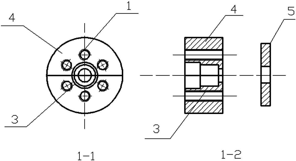
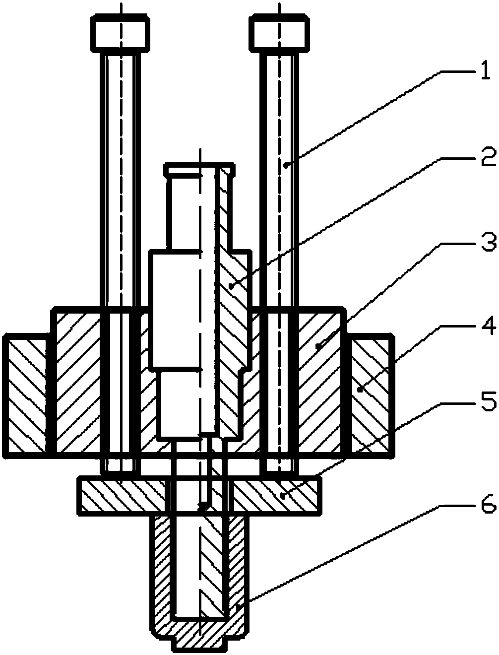
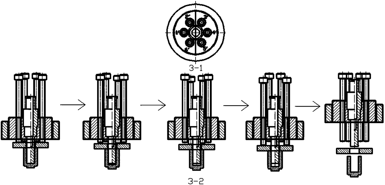
The invention provides a special progressive discharge device for a Gleeble-3500 testing machine. On one hand, the discharge device comprises two split moulds for fixing a convex mould, a fixing ringfor fastening the two split moulds and a plurality of fastening screws symmetrically distributed along the circumference of the fixing ring, and further comprises a discharge plate, wherein the numberof the fastening screws is an even number; the discharge plate is detachably mounted at the bottom of the convex mould in a clamping manner, and is used for downwardly propping a test piece to be discharged at the bottom of the convex mould. On the other hand, the invention further provides a discharging method. The discharging method comprises the following steps: after rotary extrusion, fixingthe convex mould into the two split moulds, adjusting the fastening screws to enable the fastening screws to be in contact with the discharge plate at the bottom of the convex mould, and then fastening the split moulds by using the fixing ring; numbering the fastening screws in clockwise or counterclockwise order: 1-n, where n is an even number; sequentially twisting the symmetric fastening screwsuntil the test piece is detached from the convex mould. Compared with the existing technology, a technology adopted by the invention has the advantage as follows: the discharging efficiency is increased by at least 5 times or above.

Description

technical field [0001] The invention belongs to the technical field of severe plastic deformation processing and forming of metal materials, and in particular relates to a progressive unloading device specially used for extrusion forming of a Gleeble-3500 testing machine. Background technique [0002] Traditional metal plastic deformation and upsetting, extrusion, rolling and other processed metals and their alloys cannot meet the metal properties required by the process in many aspects, so a series of equal-diameter angular extrusion, high-pressure torsion, stacking Severe plastic deformation methods such as rolling and technology and multi-directional forging. The new severe plastic method described in the invention patent application "201710544673.7", that is, rotary extrusion forming, is different from the above-mentioned severe plastic deformation process. The anisotropy of small deformation parts achieves the purpose of uniform overall performance. The special mold f...

Claims


Application Information

Patent Timeline
Patent Type & Authority Applications(China)
IPC IPC(8): B21C35/02B21C25/02
CPCB21C25/02B21C35/02
Inventor 于建民张治民屈晓晓程眉徐健许萍
Owner ZHONGBEI UNIV
Learn More