
Chaotic composite stirring system and stirring method thereof

A stirring system and a chaotic technology, which are applied to a chaotic compound stirring system and the field of stirring, can solve the problems that the tissue structure is easily damaged by shear force, the stirring speed cannot be very high, and the heat transfer effect is not obvious, so as to reduce the fluid layer. Dead zone, improved mixing efficiency, long service life

Active Publication Date: 2018-09-07
KUNMING UNIV OF SCI & TECH
View PDF8 Cites 4 Cited by
  • Summary
  • Abstract
  • Description
  • Claims
  • Application Information

AI Technical Summary

Problems solved by technology

When stirring high-viscosity materials, more energy is required, and the stirring paddle is required to withstand a large bending moment, which puts forward higher requirements for the strength of the structure; when stirring polymer materials that are sensitive to shear Because its organizational structure is easily destroyed by shear force, the stirring speed it can bear cannot be very high, and high-speed stirring will cause high-temperature melt splashing. It is difficult for ordinary mechanical stirring devices to meet the requirements, and the mixing efficiency is low. , the heat transfer effect is not obvious, and the energy consumption is huge

Method used


Image

  • Chaotic composite stirring system and stirring method thereof
  • Chaotic composite stirring system and stirring method thereof
  • Chaotic composite stirring system and stirring method thereof

Examples


Embodiment Construction

[0032] The present invention will be further described below in combination with the accompanying drawings and specific embodiments.

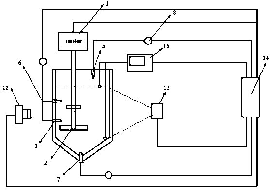
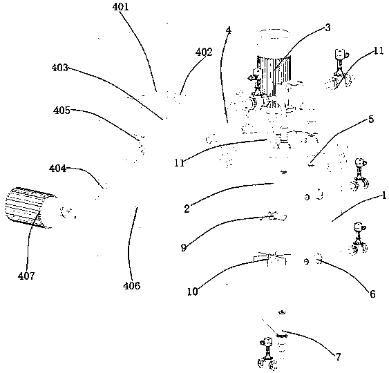
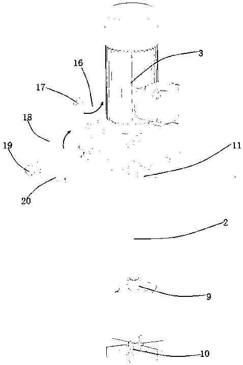
[0033] Such as Figure 1~3 As shown, a chaotic composite stirring system includes a chaotic composite stirring device and a monitoring and control system. The chaotic composite stirring device includes a stirring tank 1, a stirring component 2, a driving device 3, a transmission device 4, a top blowing swirl spray gun 5, a side blowing Swirling spray gun 6, bottom blowing swirl spray gun 7, air intake pipe I, air intake pipe II, air intake pipe III, transmission device 4 includes a driving member and a transmission member, the driving member is arranged on one side of the stirring tank 1, and the transmission member is fixedly arranged on the stirring tank 1 side. The top of the tank 1, the output end of the driving member is connected with the transmission member, the driving device 3 is fixedly arranged on the top of the transmission member, ...


PUM


Abstract

The invention relates to a chaotic composite stirring system and a stirring method thereof, and belongs to the technical field of mechanical stirring equipment. The chaotic composite stirring system comprises a chaotic composite stirring device and a monitoring control system, wherein the chaotic composite stirring device comprises a stirring tank, a stirring component, a driving device, a transmission device, a top-blown rotational flow spray gun, a side-blown rotational flow spray gun, a bottom-blown rotational flow spray gun, an air inlet pipe I, an air inlet pipe II and an air inlet pipe III; the monitoring control system comprises a high-speed camera, a laser transmitter, a processor and an electrical conductivity meter. According to the chaotic composite stirring system disclosed bythe invention, combination of mechanical stirring and rotational flow gas stirring in variable-frequency flow is adopted, the area of a chaotic mixing zone can be strengthened by freely changing an eccentricity ratio of the stirring tank, the immersion depth of a stirring shaft and a deviation angle, the gas spray quantities of rotational flow spray guns can be subjected to variable-frequency regulation in real time and can be in periodic pulsation change, the chaotic composite stirring device is enabled to realize chaotic mixing within an extremely short time under low Reynolds number flow, and the mixing efficiency and the heat and mass transfer speed of fluid materials are improved to a large extent.

Description

technical field [0001] The invention relates to a chaotic composite stirring system and a stirring method thereof, belonging to the technical field of mechanical stirring equipment. Background technique [0002] Mechanical stirring is the most common and widely used operation for mixing multiphase fluids in the metallurgical and chemical industries. When stirring high-viscosity materials, more energy is required, and the stirring paddle is required to withstand a large bending moment, which puts forward higher requirements for the strength of the structure; when stirring polymer materials that are sensitive to shear Because its organizational structure is easily destroyed by shear force, the stirring speed it can bear cannot be very high, and high-speed stirring will cause high-temperature melt splashing. It is difficult for ordinary mechanical stirring devices to meet the requirements, and the mixing efficiency is low. , the heat transfer effect is not obvious, and the ene...

Claims


Application Information

Patent Timeline
IPC IPC(8): B01F13/02B01F7/18B01F33/40
CPCB01F27/90B01F33/405B01F33/402
Inventor 王华王嘉伟王仕博
Owner KUNMING UNIV OF SCI & TECH
Learn More