
Virtual synchronous generator control method based on direct power control when grid voltage is unbalanced

A technology of generator control and grid voltage, applied in the direction of single-network parallel feeding arrangement, electrical components, circuit devices, etc., can solve the problem of unbalanced grid voltage, the influence of grid safety and stable operation, and affect the power quality and stability of virtual synchronous generators Operation and other issues, to achieve the effect of easy engineering implementation and improved dynamic response capability

Active Publication Date: 2018-09-04
JIANGXI UNIV OF SCI & TECH
View PDF5 Cites 12 Cited by
  • Summary
  • Abstract
  • Description
  • Claims
  • Application Information

AI Technical Summary

Problems solved by technology

[0003] The distributed generation unit is installed at the end of the power grid, away from the main power network, the power grid is fragile, and the power grid environment is relatively complex, the grid voltage has high harmonic content and the grid impedance is large, and grid voltage imbalance faults are prone to occur
These non-ideal grid environments will directly affect the power quality and stable operation of virtual synchronous generators, and also have a negative impact on the safe and stable operation of the grid.

Method used


Image

  • Virtual synchronous generator control method based on direct power control when grid voltage is unbalanced
  • Virtual synchronous generator control method based on direct power control when grid voltage is unbalanced
  • Virtual synchronous generator control method based on direct power control when grid voltage is unbalanced

Examples


Embodiment Construction

[0049] The present invention will be described in detail below in conjunction with the accompanying drawings and working principles.

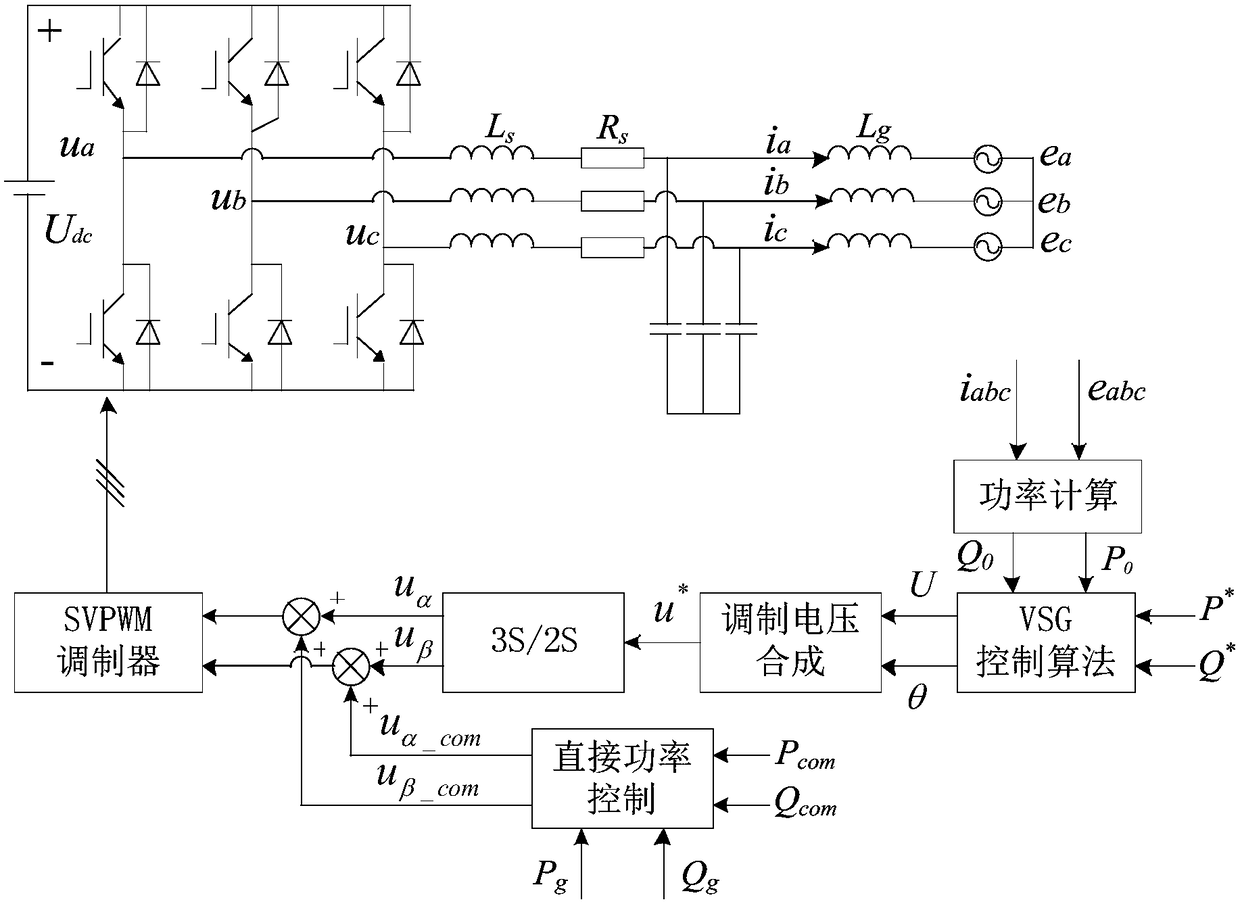
[0050] Such as figure 1 As shown in the figure, U dc is the DC side voltage, R s , L s and C are the internal resistance of the filter inductor, filter inductor and filter capacitor respectively; i a i b and i c is the inverter output current; u a , u b and u c Output three-phase voltage for the inverter side; e a 、e b and e c is the three-phase grid voltage; L g is the line inductance; P * , Q * Respectively active and reactive power given value; P g , Q g Output instantaneous active and reactive power measurement values ​​for the inverter, P 0 , Q 0 Output the average instantaneous active and reactive power measurement values ​​for the inverter. The present invention is a virtual synchronous generator control technology based on direct power control when the grid voltage is unbalanced. When the grid voltage is unbalanced, th...


PUM


Abstract

The invention provides a virtual synchronous generator control method based on direct power control when a grid voltage is unbalanced. The virtual synchronous generator control method comprises the steps of: firstly, utilizing ROGI to obtain grid voltage and grid-connected current positive sequence components, and output instantaneous power and average instantaneous power of an inverter; secondly,regarding the average instantaneous power as feedback quantities, and utilizing a traditional virtual synchronization control strategy to obtain reference modulation signals under alpha-beta stationary coordinates; thirdly, adopting a vector proportional integral resonant controller to establish a direct power control loop, regarding the output instantaneous power as feedback quantities, and utilizing direct power control to obtain modification modulation signals through setting different power instruction values separately; and finally, superimposing the reference modulation signals and themodification modulation signals to obtain a final modulation signal, and sending the final modulation signal to an SVPWM modulation module to realize two independent control targets of sinusoidal andbalanced output current and constant output power without fluctuations. The virtual synchronous generator control method reserves the original control features of the VSG, does not require a phase-locked loop, improves the dynamic response capability of the system, and is easy in engineering implementation.

Description

technical field [0001] The invention belongs to the technical field of distributed power generation, and relates to a virtual synchronous generator control method when the grid voltage is unbalanced. Background technique [0002] The development of renewable new energy and the improvement of the utilization efficiency of renewable energy are the inevitable ways to solve human energy problems. Renewable energy needs to be connected to the grid through power electronic converters, with the goal of injecting maximum power into the grid. When the installed capacity of distributed generation is relatively low, the original traditional synchronous generators in the system can provide sufficient support for the power system, and the access of distributed generation units will not pose a threat to the stability of the power system. Since the distributed generation units interfaced with power electronic converters do not have the inertia and damping of synchronous generators, with t...

Claims


Application Information

Patent Timeline
Patent Type & Authority Applications(China)
IPC IPC(8): H02J3/38
CPCH02J3/381
Inventor 胡海林刘飞飞黄秋杰刘雨峰蔡少文刘千铭
Owner JIANGXI UNIV OF SCI & TECH
Learn More