
A method for in-situ measurement of sample magnetism

An in-situ measurement and sample technology, applied in magnetic properties measurement, magnetic field size/direction, measuring devices, etc., can solve problems such as low resolution of magnetic domain images, difficult to meet accuracy requirements, and complex magnetic domain magnetization directions, etc., to achieve Increase the signal-to-noise ratio, reduce the parasitic Faraday effect, and reduce the effect of mechanical instability

Active Publication Date: 2020-04-03
嘉兴诺恩医疗科技有限公司
View PDF5 Cites 0 Cited by
  • Summary
  • Abstract
  • Description
  • Claims
  • Application Information

AI Technical Summary

Problems solved by technology

Defect 1 of the prior art: The traditional Kerr microscope uses a mechanical mechanism to adjust the aperture slit to change the illuminated area on the sample, which is difficult to meet the accuracy requirements of the experiment; Defect 2 of the prior art: some special magnetic samples, which The magnetization direction of the magnetic domain is relatively complicated, and the resolution of the magnetic domain image obtained by the Kerr microscope of the prior art is low, and the position of the slit diaphragm needs to be changed many times to find suitable incident light conditions to obtain a higher image resolution , especially when studying the magnetoelastic properties of the sample, it is necessary to have different incident light intensities in different directions, and adjust the incident light intensity according to the obtained image quality, which is time-consuming, laborious and complicated to operate. Measurements can solve the problem

Method used


Image

  • A method for in-situ measurement of sample magnetism
  • A method for in-situ measurement of sample magnetism

Examples


Embodiment Construction

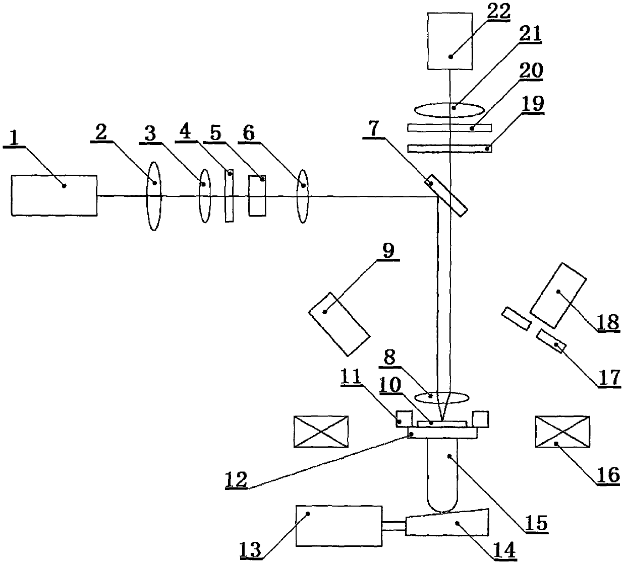
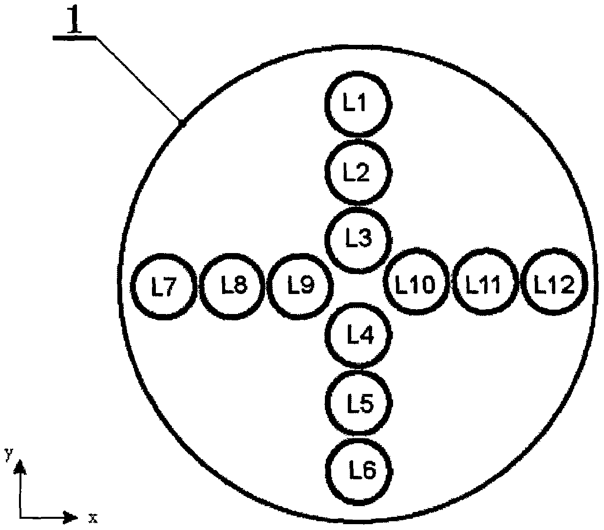
[0030] Such as figure 1 is a schematic diagram of the present invention, such as figure 2 It is an enlarged schematic diagram of the side of the light source. There is an xy two-dimensional direction mark in the lower left corner. III6, semi-transparent mirror 7, objective lens 8, laser 9, sample 10, sample stage 11, substrate 12, stepper motor 13, inclined platform 14, thimble 15, magnet 16, slit diaphragm 17, photodetector I18 , compensator 19, analyzer 20, aspheric mirror IV21, photodetector II22, described light source 1, aspheric mirror I2, aspheric mirror II3, field stop 4, polarizer 5, aspheric mirror III6, semi-transparent mirror 7. The objective lens 8 forms an illumination optical path in turn, and the objective lens 8, the semitransparent mirror 7, the compensator 19, the analyzer 20, and the aspheric mirror IV21 form an imaging optical path in turn, and the laser 9, the surface of the sample 10, and the slit diaphragm 17. The photodetector 118 forms a calibratio...


PUM

PropertyMeasurementUnit
thicknessaaaaaaaaaa

Abstract

The invention relates to the field of material surface magnetism measurement, and discloses an in-situ measurement method for sample magnetism. The in-situ measurement method adopts a measuring device, wherein the measuring device comprises a light source, an aspherical mirror I, an aspherical mirror II, a field diaphragm, a polarizer, an aspherical mirror III, a translucent reflector, an objective lens, a laser device, a sample, a sample platform, a substrate, a stepping motor, an inclined plane bench, an ejection pin, a magnet, slit diaphragms, a photoelectric detector I, a compensator, ananalyzer, an aspherical mirror IV and a photoelectric detector II. According to the in-situ measurement method, the illumination region on the sample does not need to be changed by means of the diaphragm slits, the Kerr sensitivity in different directions is measured, the mechanical instability in the experiment is reduced, incident light intensity in different directions are adjusted through adjusting the number and the duration of turned-on LED lamps, the intensity of incident light is adjusted in real time according to the acquired image quality so as to obtain an image with good resolution, and especially for some magnetic samples with complicated magnetization directions of magnetic domains, the magnetoelastic property of the sample can be studied in situ through adopting the method of applying stress to the back surface of the sample.

Description

technical field [0001] The invention relates to the field of magnetic measurement on the surface of materials, in particular to an in-situ magnetic measurement method of a sample using a special light source and a magnet structure. Background technique [0002] The magneto-optical Kerr effect measurement device is an important means in the study of material surface magnetism. Its working principle is based on the magneto-optic Kerr effect caused by the interaction between light and magnetized media. Magnetic detection, and non-contact measurement can be realized, and it has important applications in the research of magnetic order, magnetic anisotropy, interlayer coupling and phase transition behavior of magnetic ultrathin films. Kerr microscope is a commonly used device. Its working principle is: after plane polarized light interacts with the surface of a non-transparent magnetic medium, the polarization plane of the reflected light rotates clockwise or counterclockwise, and...

Claims


Application Information

Patent Timeline
Patent Type & Authority Patents(China)
IPC IPC(8): G01R33/032G01R33/12
CPCG01R33/0325G01R33/12
Inventor 张向平方晓华赵永建
Owner 嘉兴诺恩医疗科技有限公司
Learn More