
Integrated waste gas bypass turbo machine with airflow management device at turbine end

An air flow management, integrated technology, applied in mechanical equipment, engine components, combustion engines, etc., can solve problems such as unfavorable engine economic improvement, reduced turbine efficiency, unstable airflow, etc., to improve turbine efficiency and improve mixing loss. , The effect that is conducive to the flow of air

Inactive Publication Date: 2018-09-04
康跃科技(山东)有限公司
View PDF0 Cites 0 Cited by
  • Summary
  • Abstract
  • Description
  • Claims
  • Application Information

AI Technical Summary

Problems solved by technology

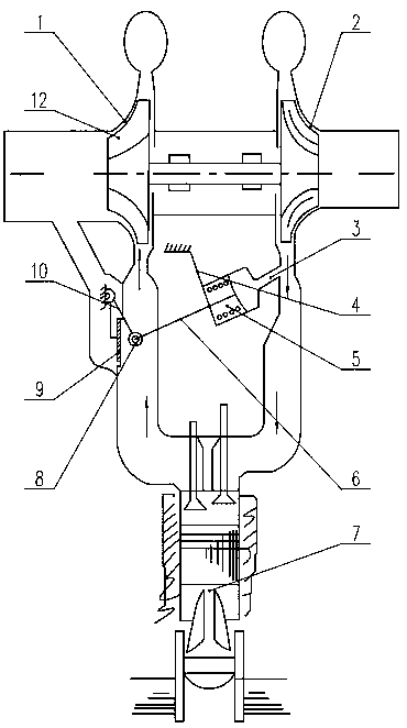
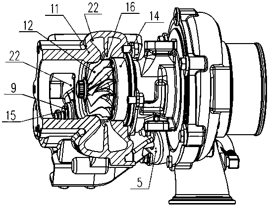
There are large differences in the exhaust temperature, flow velocity and pressure of the two airflows, and they are violently mixed in the exhaust duct 22 of the turbine casing, which is close to the turbine, resulting in unstable flow of the airflow, resulting in airflow loss, reducing the efficiency of the turbine, and is not conducive to the engine Improved economy, at the same time the unstable flow of the airflow also creates noise problems

Method used


Image

  • Integrated waste gas bypass turbo machine with airflow management device at turbine end
  • Integrated waste gas bypass turbo machine with airflow management device at turbine end
  • Integrated waste gas bypass turbo machine with airflow management device at turbine end

Examples


Embodiment 1

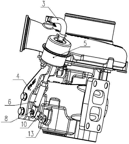
[0037] Such as Figure 4 , Figure 5 , Figure 6 and Figure 7 Commonly shown, the integrated wastegate turbine with airflow management device at the vortex end includes a turbine casing 11 and an integrated turbine casing cover plate 18 installed at the outlet end of the turbine casing 11, and also includes a bypass exhaust gas passage 19 and a turbine exhaust gas passage 20 . The turbine casing 11 is provided with a turbine 12 and an intake runner 22 . Both the bypass exhaust gas channel 19 and the turbine exhaust gas channel 20 extend from the turbine housing 11 to the integrated turbine housing cover plate 18 . The bypass exhaust gas channel 19 and the turbine exhaust gas channel 20 each manage two air flows. The integrated turbine casing cover plate 18 is provided with a diversion groove 21 , and the bypass exhaust gas passage 19 and the turbine exhaust gas passage 20 are connected through the diversion groove 21 . The guide groove 21 is arranged on the integrated t...

Embodiment 2

[0041] Such as Figure 8 and Figure 9 Commonly shown, the integrated wastegate turbine with airflow management device at the vortex end includes a turbine casing 11 and an integrated turbine casing cover plate 18 installed at the outlet end of the turbine casing 11, and also includes a bypass exhaust gas passage 19 and a turbine exhaust gas passage 20 . The turbine casing 11 is provided with a turbine 12 and an intake runner 22 . Both the bypass exhaust gas channel 19 and the turbine exhaust gas channel 20 extend from the turbine housing 11 to the integrated turbine housing cover plate 18 . The bypass exhaust gas channel 19 and the turbine exhaust gas channel 20 each manage two air flows. The integrated turbine casing cover plate 18 is provided with a diversion groove 21 , and the bypass exhaust gas passage 19 and the turbine exhaust gas passage 20 are connected through the diversion groove 21 . The guide groove 21 is arranged on the integrated turbine casing cover plate ...

Embodiment 3

[0044] Such as Figure 10 and Figure 11 Commonly shown, the integrated wastegate turbine with airflow management device at the vortex end includes a turbine casing 11 and an integrated turbine casing cover plate 18 installed at the outlet end of the turbine casing 11, and also includes a bypass exhaust gas passage 19 and a turbine exhaust gas passage 20 . During use, the integrated turbine casing cover plate 18 is connected with the total exhaust pipe 23 of the engine. The turbine casing 11 is provided with a turbine 12 and an intake runner 22 . Both the bypass exhaust gas channel 19 and the turbine exhaust gas channel 20 extend from the turbine housing 11 to the integrated turbine housing cover plate 18 . The bypass exhaust gas channel 19 and the turbine exhaust gas channel 20 each manage two air flows. The integrated turbine casing cover plate 18 is provided with a diversion groove 21 communicating with the bypass waste gas passage 19 . The diversion groove 21 is arran...


PUM


Abstract

The invention discloses an integrated waste gas bypass turbo machine with an airflow management device at the turbine end. The integrated waste gas bypass turbo machine comprises a turbine shell, a bypass waste gas channel and a turbine waste gas channel, as well as an integrated turbine shell cover plate which is arranged at the air outlet end of the turbine shell; both the bypass waste gas channel and the turbine waste gas channel extend from the turbine shell to the integrated turbine shell cover plate; and flow guide grooves are formed in the integrated turbine shell cover plate, the bypass waste gas channel and the turbine waste gas channel communicate with each other through the flow guide grooves, and the flow guide grooves are formed in the position, away from a turbine, of the integrated turbine shell cover plate. According to the integrated waste gas bypass turbo machine with the airflow management device at the turbine end, the bypass waste gas and the waste gas entering theturbine are naturally mixed in an exhaust passage which is far away from the turbine, and the impact is relatively small when the two strands of airflow are converged; and the advantages of being small in airflow loss, low in noise, high in turbo machine efficiency and the like are achieved.

Description

technical field [0001] The invention relates to a turbine on a turbocharger, in particular to an integrated waste gas bypass turbine with an airflow management device at the vortex end, and belongs to the field of internal combustion engines. Background technique [0002] The speed range of the vehicle engine is wide, and the supercharger is required to have good responsiveness, high torque at medium and low speeds, high torque reserve coefficient, and high rated power. In order to realize the matching of all working conditions of vehicle engines, wastegate turbochargers are generally used in vehicle engines. [0003] To meet these requirements, the wastegate turbocharger is designed with a turbine with a smaller flow capacity and a smaller compressor to increase the boost pressure and intake air flow in the low-speed section to meet the low- and medium-speed torque characteristics, smoke emission and response. sexual issues. Due to the design of a turbine with a small flo...

Claims


Application Information

Patent Timeline
Patent Type & Authority Applications(China)
IPC IPC(8): F02B37/02F02B37/18F01D25/24
CPCF01D25/24F02B37/025F02B37/18F05D2220/40Y02T10/12
Inventor 李延昭李伟张金明邵同林苏益龙叶文婷
Owner 康跃科技(山东)有限公司
Learn More