
Rotary clamp for automatic production line of leather products

An automated production line and rotary fixture technology, applied in leather, household appliances, applications, etc., can solve problems such as lack of good protection devices or packaging structures, leather products are easily stained with dust or moisture, and affect the quality and fineness of leather products. , to achieve the effect of saving pressing mechanism and heat sealing device, saving drying time and manpower

Active Publication Date: 2018-09-04
重庆瑞丰精密模具有限公司
View PDF8 Cites 4 Cited by
  • Summary
  • Abstract
  • Description
  • Claims
  • Application Information

AI Technical Summary

Problems solved by technology

[0008] (1) The leather needs to be dried before processing, and the drying speed is slow. The ordinary air dryer can only dry one side of the leather at a time, and the leather is still when it is blown by the wind, so the leather In some places, the hot air cannot be blown, resulting in slow drying of the leather and prolonging the production time of the production line;
[0009] (2) After the leather products are painted or dyed, the bags are usually dried naturally, which will greatly reduce the production efficiency of the production line;
[0010] (3) When leather products are stitched, most of the time they are manually operated, and only one side of the leather can be sewn each time, and the production efficiency is low;
[0011] (4) After the leather products are processed, they are usually gathered together without a good protection device or packaging structure, resulting in the leather products being easily stained with dust or damp, affecting the quality and fineness of the leather products

Method used


Image

  • Rotary clamp for automatic production line of leather products
  • Rotary clamp for automatic production line of leather products
  • Rotary clamp for automatic production line of leather products

Examples


Embodiment Construction

[0061] The technical solutions in the embodiments of the present invention will be clearly and completely described below with reference to the accompanying drawings in the embodiments of the present invention. Obviously, the described embodiments are only a part of the embodiments of the present invention, but not all of the embodiments. Based on the embodiments of the present invention, all other embodiments obtained by those of ordinary skill in the art without creative efforts shall fall within the protection scope of the present invention.

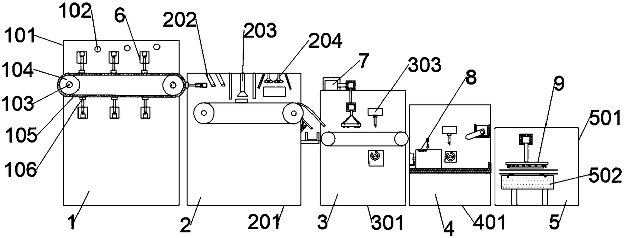
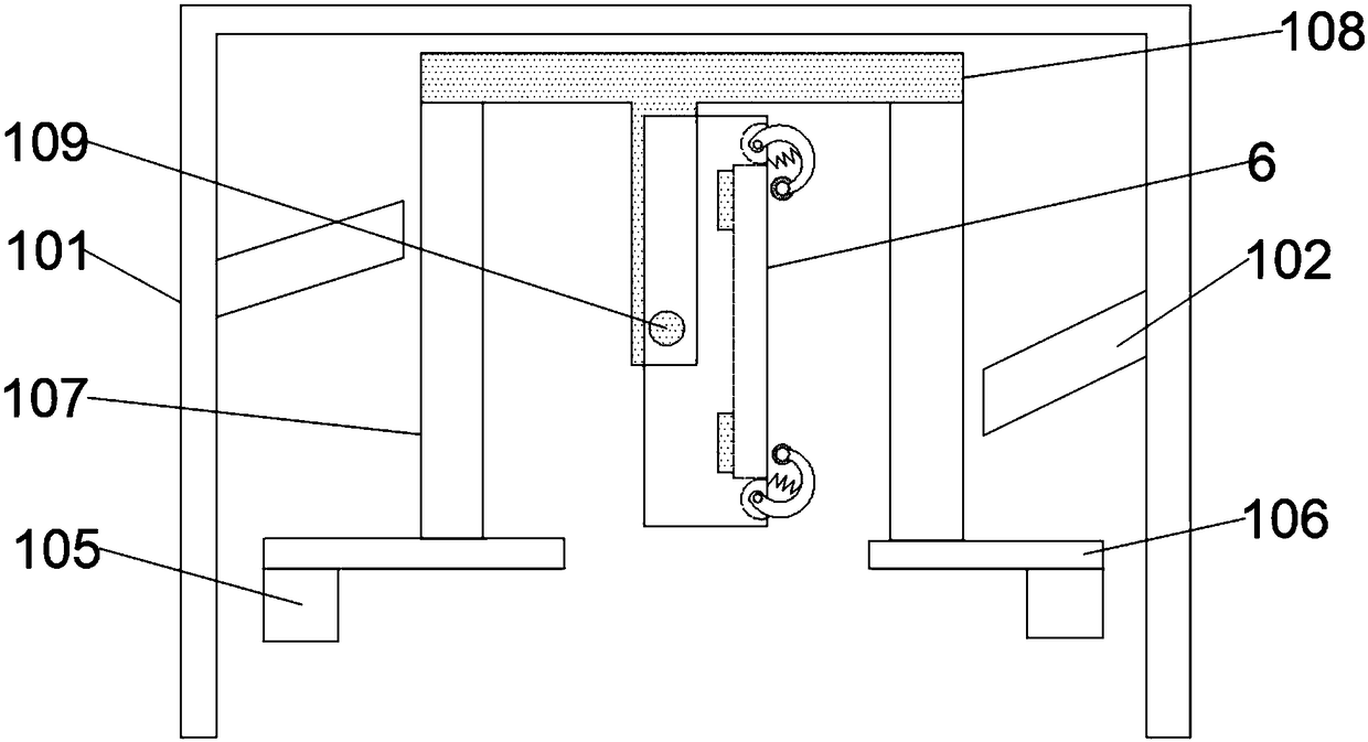
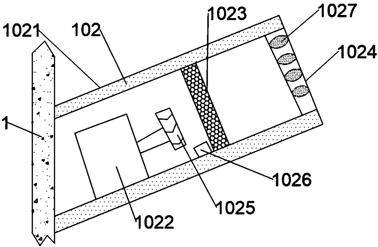
[0062] like Figure 1 to Figure 3 As shown, the present invention provides a rotating fixture for an automatic production line of leather products, including a high-efficiency leather drying device 1, and the high-efficiency leather drying device 1 includes a mounting frame 101, and the right end of the mounting frame 101 is provided with a coating Color device 2, several hot air devices 102 are installed at the front and rear ends of...


PUM


Abstract

The invention discloses a rotary clamp for an automatic production line of leather products. The rotary clamp comprises a rotary clamp base, the rotary clamp base comprises a clamping base with a square normal section, and a cross bearing strip is arranged at the bottom of the clamping base; a leather groove is formed in the inner side of the top of the clamping base, and a plurality of balancingweights are further installed at the top of the clamping base; a plurality of leather clamping devices are arranged on the clamping base; each leather clamping device comprises a plurality of U-shapedclamping arms which are hinged to the top of the clamping base, and the bottoms of the U-shaped clamping arms are provided with iron pressing rods above the side of the leather groove; one side of each U-shaped clamping arm is connected with the clamping base through a spring, a rubber sleeve sleeves the outer side of each iron pressing rod, and electromagnets corresponding to the iron pressing rods in position are arranged at the bottom of the leather groove; by means of the cross bearing strip, when leather is placed in the leather groove, the situation that middle of the leather is concavedue to gravity is avoided; the top face of the cross bearing strip and the bottom face of the leather groove are located on the same plane so that the leather can be placed in the leather groove moresmoothly.

Description

technical field [0001] The invention relates to the field of leather production lines, in particular to a rotary clamp used for an automatic production line of leather products. Background technique [0002] Leather is a denatured and non-perishable animal skin obtained by physical and chemical processing such as depilation and tanning. Leather is composed of natural protein fibers tightly woven in three-dimensional space, and its surface has a special grain layer, which has natural grain and luster, and feels comfortable. [0003] The leather industry covers the main industries such as tanning, shoemaking, leather clothing, leather goods, fur and its products, as well as supporting industries such as leather chemicals, leather hardware, leather machinery, and accessories. The upstream and downstream are highly correlated, relying on the market to drive, the products are evergreen, and the characteristics of the combination of earning foreign exchange, enriching the people,...

Claims


Application Information

Patent Timeline
IPC IPC(8): B68F1/00B65B53/02
CPCB65B53/02B68F1/00
Inventor 周磊
Owner 重庆瑞丰精密模具有限公司
Learn More