Machine vision based ultrasonic object cutting device and cutting method thereof

A technology of machine vision and cutting equipment, which is applied in metal processing and other directions, can solve the problems of increased cutting failure rate, unsuitable for large-scale production, and low cutting precision, so as to improve flexibility and controllability, realize large-scale production, The effect of improving cutting efficiency

Pending Publication Date: 2018-09-04
广东赛德英斯智能装备有限公司 +1
View PDF3 Cites 1 Cited by
  • Summary
  • Abstract
  • Description
  • Claims
  • Application Information

AI Technical Summary

Problems solved by technology

However, this traditional way of cutting items not only has the disadvantages of serious deformation of the item, more debris, and rough cutting surface during the cutting process, but also requires regular cleaning of the knife due to the sticking phenomenon of the item, especially when processing items like cream pastry and chocolate. For materials that are easy to stick to knives such as sandwiches and sandwiches, the traditional method of cutting items greatly reduces production efficiency
[0004] In addition, the traditional article cutting production line cannot accurately locate the article, resulting in low cutting accuracy and cutting precision, which not only increases the cutting failure rate and causes article waste, but also greatly reduces the quality of article cutting and affects the subsequent packaging of articles. Production of products and other processes
In addition, the existing article cutting method also has low production efficiency, which makes it unsuitable for large-scale production

Method used


Image

  • Machine vision based ultrasonic object cutting device and cutting method thereof
  • Machine vision based ultrasonic object cutting device and cutting method thereof
  • Machine vision based ultrasonic object cutting device and cutting method thereof

Examples


Embodiment

[0062] In this embodiment, the items cut by the equipment will be described below by taking sandwich food as an example.

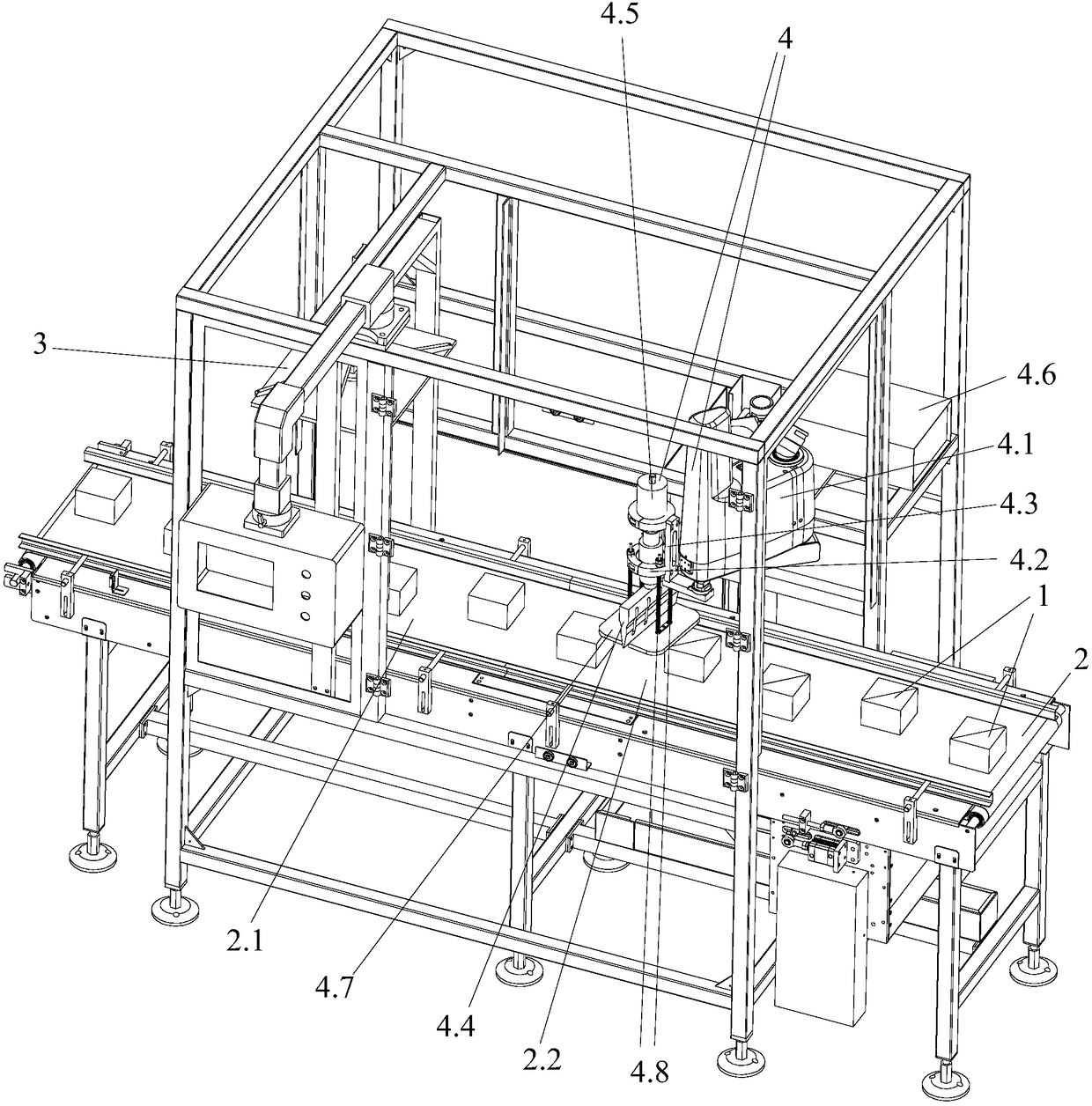
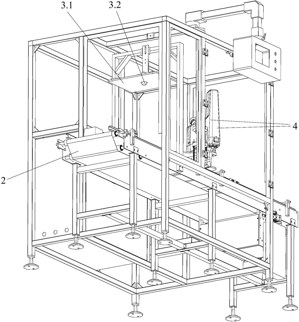
[0063] like figure 1 and figure 2 As shown, a kind of ultrasonic article cutting equipment based on machine vision of the present invention comprises:

[0064] The conveying mechanism is used to convey the article 1. The conveying mechanism includes a conveying belt 2 and a servo motor for driving the conveying belt 2, wherein the conveying belt 2 is divided into an image acquisition area 2.1 and a cutting area 2.2 in sequence along the conveying direction; during operation, the conveying The mechanism transfers the item 1 to the image acquisition area 2.1 and the cutting area 2.2 in sequence;

[0065] The machine vision mechanism 3 is used for image acquisition of the item 1 transmitted to the image acquisition area 2.1, and serves as a starting position for obtaining tracking and positioning information;

[0066] The article cutting mechanism 4 is us...


PUM


Abstract

The invention provides a machine vision based ultrasonic object cutting device. The device comprises a conveying mechanism for sequentially conveying objects to an image acquiring area and a cutting area, a machine vision mechanism for acquiring a starting position for of tracking positioning information, an object cutting mechanism for adjusting the cutting parameters and selecting the cutting mode based on the tracking positioning information and then performing tracking type or fixed point type positioning and cutting on the objects conveying in the cutting area by ultrasonic cutting, and acontroller, wherein the machine vision mechanism is arranged above the image acquiring area in a conveyor belt; and the object cutting mechanism is arranged above the cutting area in the conveyor belt. The device has the characteristics of being fast to cut, prevented from adhering to a cutter after cutting, and hard to deform during object cutting; the object cutting efficiency, precision and accuracy can be improved. The invention also provides a high cutting speed and high cutting precision type machine vision based ultrasonic object cutting method. With the adoption of the method, the object cutting efficiency and accuracy can be improved.

Description

technical field [0001] The invention relates to the technical field of article cutting, and more specifically, relates to a machine vision-based ultrasonic article cutting device and a cutting method thereof. Background technique [0002] Article cutting machinery is an emerging industry. With the improvement of people's living standards, the requirements for articles are increasing year by year, and the requirements for the quality and hygiene of articles are becoming stronger and stronger. [0003] Most of the traditional article cutting production lines cut articles, unfired mud bricks, soap, small tablets and other articles. Now they all use mechanical cutting such as hob mechanism to cut the articles through extrusion deformation and shear force. However, this traditional way of cutting items not only has the disadvantages of serious deformation of the item, more debris, and rough cutting surface during the cutting process, but also requires regular cleaning of the knif...

Claims


Application Information

Patent Timeline
IPC IPC(8): B26F3/00B26D5/02B26D7/06B26D7/01
CPCB26D5/007B26D5/02B26D7/01B26D7/0625B26F3/00
Inventor 黄振飞曾庆寿
Owner 广东赛德英斯智能装备有限公司
Why Eureka
Try Eureka