Hardware punching device

A stamping device and hardware technology, applied in the field of hardware processing, can solve the problems of affecting the stamping progress, plate waste, affecting the continuous processing of ring gaskets, etc., and achieve the effect of continuous stamping and plate saving

Inactive Publication Date: 2018-09-04
宁波得晴电器科技有限公司
View PDF0 Cites 7 Cited by
  • Summary
  • Abstract
  • Description
  • Claims
  • Application Information

AI Technical Summary

Problems solved by technology

[0003] In order to realize the continuous punching of ring gaskets, usually a larger plate is placed on the conveyor belt for stamping during transmission, so as to obtain multiple ring gaskets; but the conveyor belt is also running during the movement of the first mold, This time difference will lead to waste of plates during the second stamping
If the conveyor belt is stopped every time punching, on the one hand, the plate will slide forward under inertia, which will also lead to waste of the plate, and on the other hand, it will also affect the stamping progress under the condition that the driving mechanism is easy to be damaged
At the same time, due to the annular structure of the ring gasket, the plate in the hollow part of the ring gasket will inevitably be discarded after stamping, which will also cause waste of the plate. Moreover, the ring gasket after stamping is inconvenient to take, which also affects the thickness of the ring gasket. One reason for continuous processing

Method used


Image

  • Hardware punching device
  • Hardware punching device
  • Hardware punching device

Examples


Embodiment Construction

[0019] Further detailed explanation through specific implementation mode below:

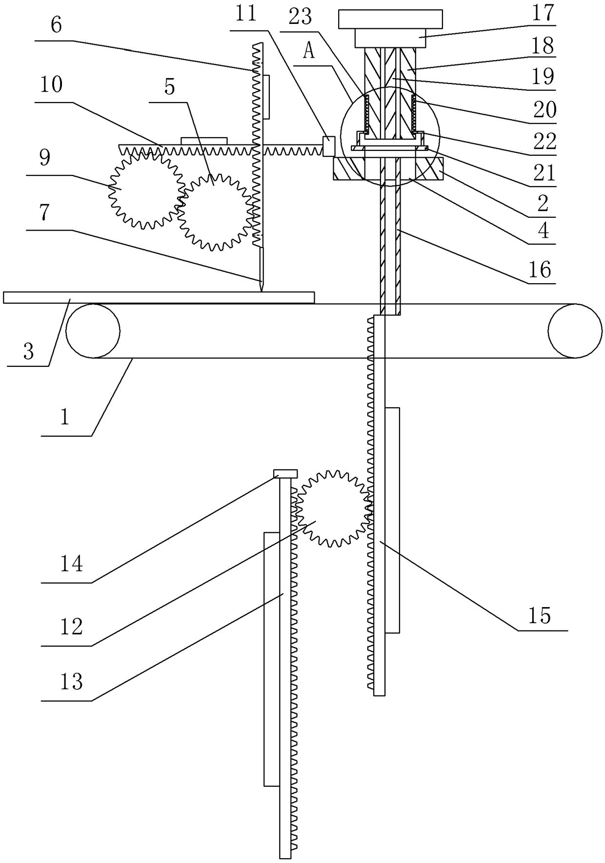
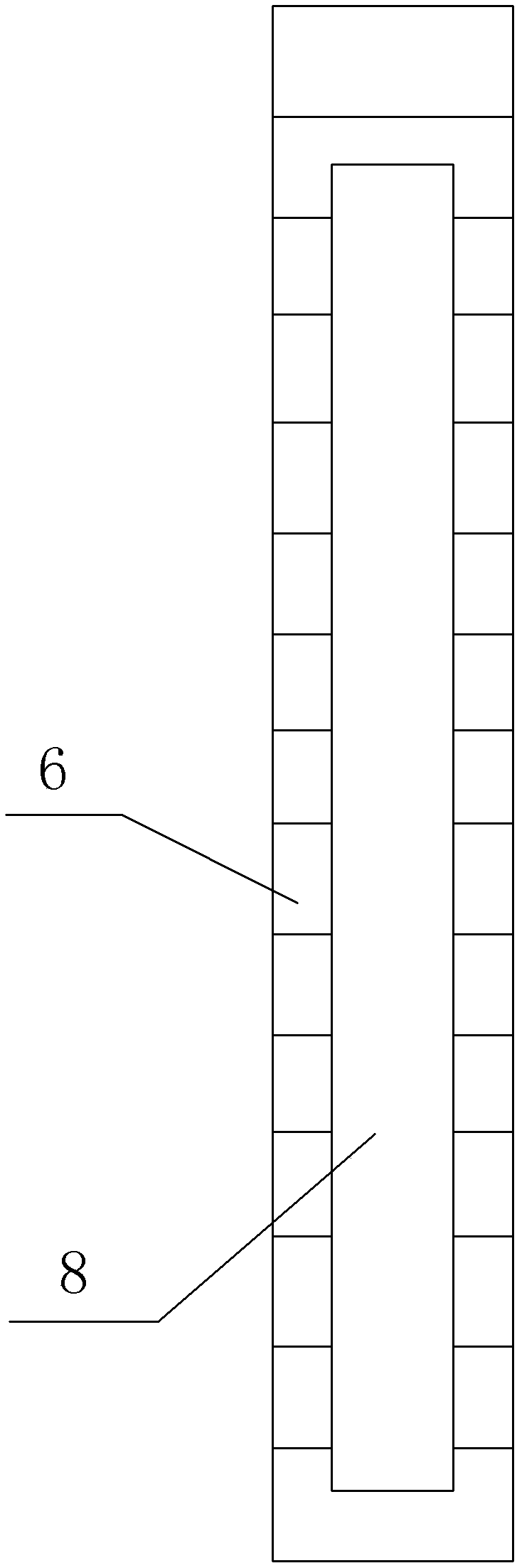
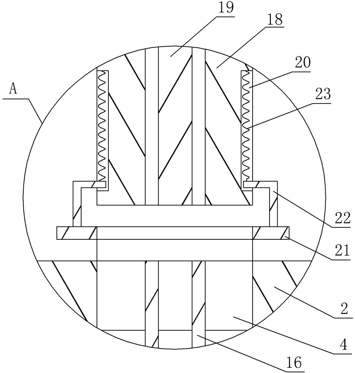
[0020] The reference signs in the accompanying drawings of the description include: the first conveyor belt 1, the stamping table 2, the plate 3, the through hole 4, the first gear 5, the first rack 6, the cutting knife 7, the channel 8, the second gear 9, the first Two racks 10, push block 11, third gear 12, third rack 13, transfer block 14, fourth rack 15, auxiliary stamping tube 16, punch 17, annular stamping tube 18, auxiliary stamping rod 19, Groove 20, positioning block 21, support rod 22, spring 23.

[0021] Such as figure 1 The hardware stamping device shown includes a transfer mechanism, a first conveyor belt 1, a second conveyor belt, a cutting and pushing mechanism, a stamping table 2 and a stamping mechanism from bottom to top. The first conveyor belt 1 and the second conveyor belt are arranged side by side on the frame, wherein the first conveyor belt 1 is located in front of the s...


PUM


Abstract

The invention relates to the field of hardware part processing, and specifically relates to a hardware punching device. The device comprises a rack, two conveyor belts, a punching platform, a cuttingpushing mechanism, a transferring mechanism and a punching mechanism, wherein the cutting pushing mechanism comprises a cutting unit and a pushing unit; the cutting unit comprises a first gear, a first rack and a cutting tool; a channel is arranged on the first rack; the pushing unit comprises a second gear and a second rack; the second rack passes through the channel; the transferring mechanism comprises a third gear, a third rack, a fourth rack and an assistant punching pipe; the punching mechanism comprises a positioning unit, an annular punching pipe and an assistant punching rod; a plurality of grooves are axially formed in the outer wall of the annular punching pipe; and the positioning unit comprises a positioning block, supporting rods which are as many as the grooves, and springs.According to the technical scheme, the device has the advantages that boards can be saved, and annular spacers can be continuously processed.

Description

technical field [0001] The invention relates to the field of hardware processing, in particular to a stamping device for hardware. Background technique [0002] As a sealing component, ring gaskets are widely used in various equipment and components, and consume a lot in components such as flanges. A typical annular gasket processing equipment is a punch press, which includes a power mechanism, which is usually provided by an external power source, and the power mechanism drives the first die to move up and down, the second die is fixed at an appropriate position on the punch press, and the first die The surface opposite to the second mold has a matching shape, so that when the punch press is working, the first mold and the second mold can be extruded to obtain an annular gasket of expected specification and shape. During the processing of the ring gasket, it is first necessary to turn on the power and start the punching machine. The power mechanism drives the first mold to...

Claims


Application Information

Patent Timeline
Patent Type & Authority Applications(China)
IPC IPC(8): B21D28/02B21D28/14B21D28/00B21D43/12B21D43/02B21D45/02
CPCB21D28/02B21D28/002B21D28/14B21D43/02B21D43/12B21D45/02
Inventor 许根海
Owner 宁波得晴电器科技有限公司
Why Eureka
Try Eureka