
Output laser positioning device with air suction channel

An inspiratory channel and laser positioning technology, which is applied in the field of medical devices, can solve the problems affecting treatment, the laser output positioning device does not have an inspiratory channel, and the output laser power is weakened, so as to simplify the production process, omit the disinfection procedure, and avoid individual pollution effect

Pending Publication Date: 2018-09-04
上海旸宸医疗科技有限公司
View PDF5 Cites 1 Cited by
  • Summary
  • Abstract
  • Description
  • Claims
  • Application Information

AI Technical Summary

Problems solved by technology

[0003] 1. The lens of the lens at the end of the laser light guide arm is easily covered by a large number of skin debris generated by the treatment, resulting in weakened output laser power and affecting treatment
The current solution is to connect an air blowing pipe to the side wall of the laser output positioning device. The air blowing pipe opens on the inner wall of the laser output positioning device. Due to the unreasonable existing design, the air blowing channel does not form a closed space, resulting in the removal of the blown gas. The skin debris is inefficient and frequently affects the positioning of the indicator light and the emission of the laser. It is necessary to stop the treatment frequently and wipe the end lens of the laser light guide arm to continue working;
[0004] 2. The laser output positioning device of the current fractional laser treatment system does not have an inhalation channel. During clinical operations, an independent assistant is required to operate the smoking pipe of the smoke purifier immediately, and closely cooperate with the laser output positioning device of the fractional laser treatment system. To a certain extent, remove harmful fumes generated by laser treatment
The setting of the smoking hood increases the volume of the original laser positioning device body, which is not convenient for clinicians to hold and operate with one hand, and it is also not convenient for laser output positioning

Method used


Image

  • Output laser positioning device with air suction channel
  • Output laser positioning device with air suction channel
  • Output laser positioning device with air suction channel

Examples


Embodiment 1

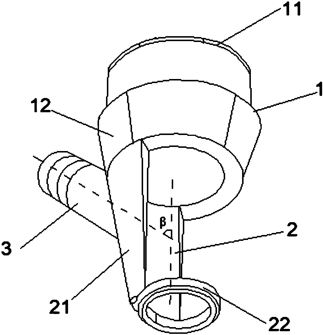
[0035] Such as figure 1As shown, an output laser positioning device with an air suction channel includes an installation section 1 installed with the end of the laser light guide arm and a positioning section 2 for positioning the output laser focal length of the laser light guide arm. The installation section 1 includes a laser light guide arm mounting part 11 and an installation section base 12, and the installation section 1 is connected with the positioning section 2 through the installation section base 12; the positioning section 2 is a semi-tubular structure (its corresponding central angle is 120 °), the positioning section pipe wall 21 is provided with an air suction channel 3 (the angle β formed by the axis line of the air suction channel and the axis line of the installation section is 45 °), the free end of the positioning section 2 is set There is a positioning ring 22; the base 12 of the mounting section and the positioning section 2 are of an integrated structur...

Embodiment 2

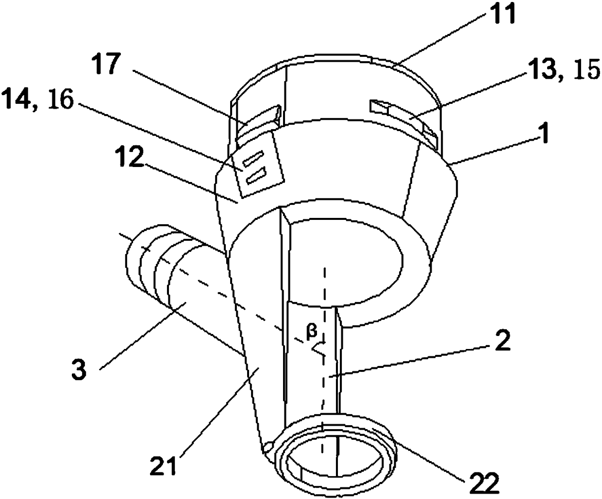
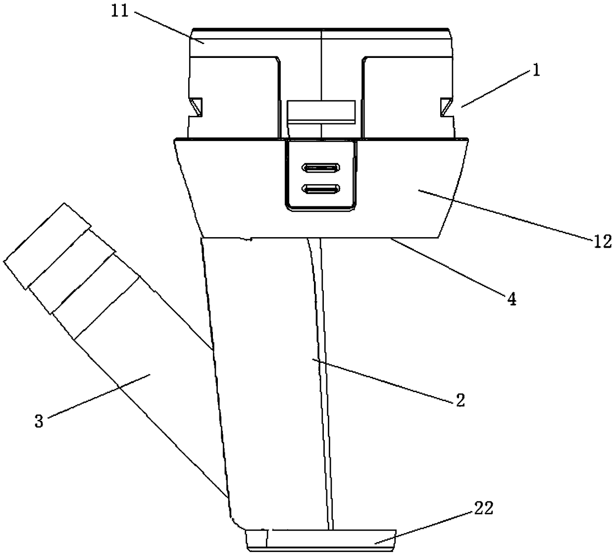
[0038] Such as figure 2 , 3 As shown, an output laser positioning device with an air suction channel includes an installation section 1 installed with the end of the laser light guide arm and a positioning section 2 for positioning the output laser focal length of the laser light guide arm. The installation section 1 includes a laser light guide arm installation part 11 and an installation section base 12 , and the installation section 1 is connected to the positioning section 2 through the installation section base 12 . The positioning section 2 is a semi-tubular structure (the corresponding central angle is 150 °), and the positioning section pipe wall 21 is provided with an air suction channel 3 (the axis line of the air suction channel and the axis line of the installation section are formed The included angle β is 60°), the free end of the positioning section 2 is provided with a positioning ring 22, and the positioning ring is a closed ring.

[0039] The optical lens ...

Embodiment 3

[0041] An output laser positioning device with an air suction channel, the rest are the same as in Embodiment 2, the laser light guide arm mounting part 11 is 2 to 8 raised structures, which are arranged on the base 12 of the mounting section, and these raised structures can be Cooperate with the end structure of the laser light guide arm.

[0042] Described positioning section 2 is tubular transparent structure (its corresponding central angle is 180 °), is set to transparent structure and is convenient to see internal treatment situation; Positioning section tube wall 21 is provided with suction channel 3 (the axis of suction channel The angle β formed with the axis line of the installation section is 45°), the free end of the positioning section 2 is provided with a positioning ring 22, and the positioning ring is a circular ring with a gap.


PUM


Abstract

The invention provides an output laser positioning device with an air suction channel. The output laser positioning device comprises a mounting section mounted at the tail end of a laser guiding arm,and a positioning section for positioning the focal length of an output laser of the laser guiding arm. The mounting section comprises a laser guiding arm mounting piece and a mounting section base. The mounting section is connected with the positioning section through the mounting section base. The positioning section is of a semi-tubular structure. The pipe wall of the positioning section is provided with the air suction channel. The free end of the positioning section is provided with a positioning ring. The output laser positioning device has the functions that exuvium of a lens at the tail end of the laser guiding arm of a fractional laser system is efficiently removed, and meanwhile, harmful smoke generated in therapy is sucked and removed in an integrated mode.

Description

technical field [0001] The invention relates to the technical field of medical devices, in particular to an output laser positioning device with an air suction channel. Background technique [0002] Fractional laser technology is a widely used skin beauty and scar treatment technology in the world. Its working scene is to irradiate the treatment area with tiny laser beams arranged in a dot matrix issued by the fractional laser treatment system, and make tiny holes on the skin and scars. , so as to form a three-dimensional lattice gasification zone in the skin and scar layer, and then cause a series of skin and scar reactions, stimulating the skin and scars to repair themselves. Achieve the effect of firming, rejuvenating, removing stains and improving scars. It is a minimally invasive treatment between invasive and non-invasive. Its clinical advantages are clear effect, less damage and short downtime, which is very popular among doctors and patients. However, in the appli...

Claims


Application Information

Patent Timeline
Patent Type & Authority Applications(China)
IPC IPC(8): A61B18/20
CPCA61B18/20A61B2018/2025A61B2218/008A61B2218/007A61B2018/00595A61B2018/0047A61B2018/20553
Inventor 杨锟
Owner 上海旸宸医疗科技有限公司
Learn More