A dual-mode Raman-optical projection tomography system

An optical projection tomography and imaging system technology, applied in Raman scattering, optical radiation measurement, material analysis through optical means, etc., can solve problems such as cytotoxicity, limited imaging performance, limited fluorescent markers, etc., and achieve fast Three-dimensional volume imaging, wide application prospects, and the effect of simple image fusion

Active Publication Date: 2020-11-24
XIDIAN UNIV
View PDF9 Cites 0 Cited by
  • Summary
  • Abstract
  • Description
  • Claims
  • Application Information

AI Technical Summary

Problems solved by technology

However, this method cannot achieve a good three-dimensional imaging effect on large-scale samples, and it cannot provide structural image information of the samples.
Although there are many methods to achieve three-dimensional volume imaging of samples, these methods are either limited by the problem of fluorescent markers or limited by imaging performance, and can only provide a single information of structure or chemical composition, and cannot simultaneously acquire multiple Modal Image Information
[0003] To sum up, the problems existing in the existing technology are: the three-dimensional volume imaging of the sample by the existing technology is limited by the fluorescent markers and imaging performance, and can only provide a single information on the structure or chemical composition, and cannot simultaneously obtain multimodal Image information
1. The impact of fluorescent markers. The fluorescent markers used in the existing imaging process will bring some serious problems, such as strong perturbation of biological system functions, non-specific targeting, cytotoxicity, etc.; 2. The imaging scale is small, and currently The method of label-free three-dimensional imaging is generally only a few hundred microns in scale; 3. The imaging process only obtains a single piece of information, either to obtain a structural image without the ability to see molecular function changes, or to obtain a label-free functional image, but it is impossible to determine its Structure and location information

Method used


Image

  • A dual-mode Raman-optical projection tomography system
  • A dual-mode Raman-optical projection tomography system
  • A dual-mode Raman-optical projection tomography system

Examples


Embodiment Construction

[0053] In order to make the object, technical solution and advantages of the present invention more clear, the present invention will be further described in detail below in conjunction with the examples. It should be understood that the specific embodiments described here are only used to explain the present invention, not to limit the present invention.

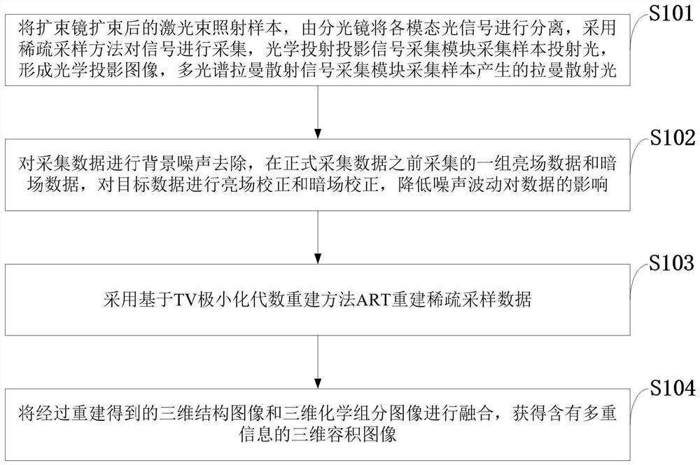
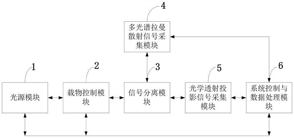
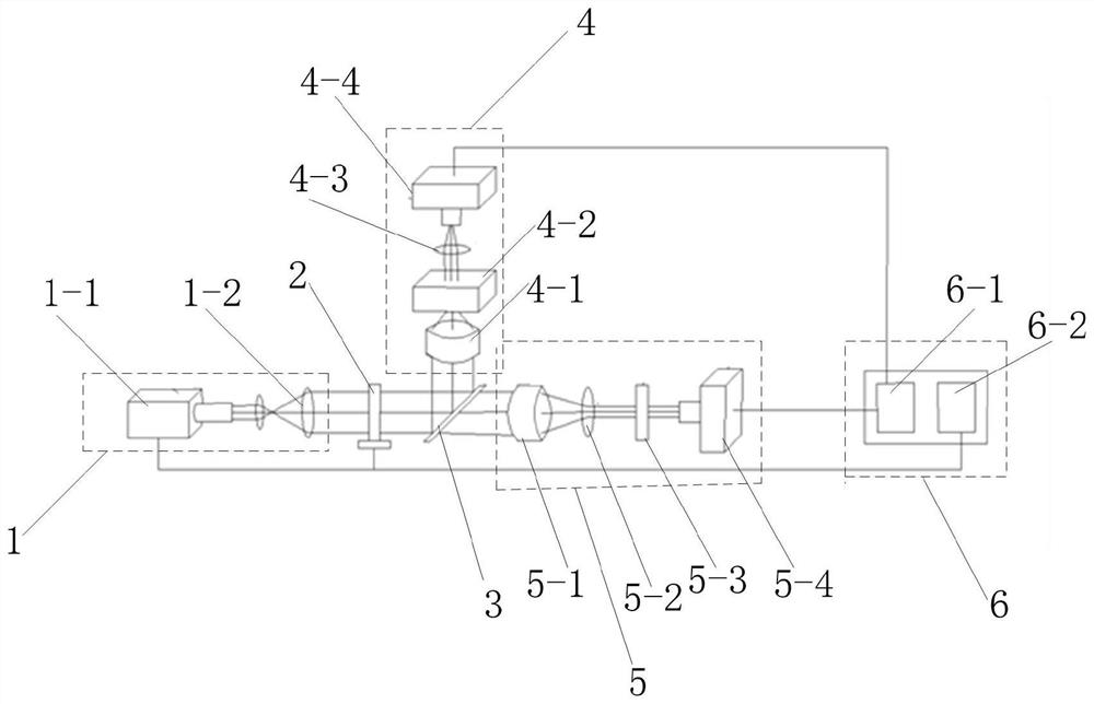
[0054] The invention can simultaneously provide the chemical component distribution image, the structural image and the chemical component spectral information of the sample to be tested. The invention provides a dual-mode tomographic imaging system capable of performing Raman spectral imaging and optical projection imaging at the same time; Raman spectral imaging can provide chemical component distribution information and spectral information of samples, and optical projection imaging can provide structural information of samples , to realize the simultaneous imaging of the chemical composition and structural information o...


PUM


Abstract

The invention belongs to the technical field of testing or analyzing materials by measuring their chemical or physical properties. It discloses a dual-mode Raman-optical projection tomography system. The laser beam is expanded by a beam expander and irradiated onto the sample. The mirror separates the light signals of each mode and uses sparse sampling to collect the signals. The optical transmission projection signal acquisition module collects the transmitted light of the sample to form an optical projection image; the multispectral Raman scattering signal acquisition module collects the Raman scattered light generated by the sample; Background noise is removed from the collected data; the sparse sampling data is reconstructed using ART based on TV minimization algebraic reconstruction; the reconstructed three-dimensional structural image and the three-dimensional chemical component image are fused to obtain a three-dimensional volume image containing multiple information. The invention cleverly combines Raman spectrum imaging and optical projection tomography imaging into the same system, providing triple information with high information fit; large-scale sample imaging speed is fast, and the operation is simple and flexible.

Description

technical field [0001] The invention belongs to the technical field of testing or analyzing materials by means of measuring their chemical or physical properties, and in particular relates to a dual-mode Raman-optical projection tomography system. Background technique [0002] At present, the existing technology commonly used in the industry is as follows: 3D volumetric imaging enables quantitative and global measurement of complex systems, which is crucial in the study of cell metabolism, brain function, and developmental biology. The easiest way to achieve 3D volumetric imaging is to use optical slice scanning. The laser is scanned on a 2D plane to collect 2D images, and the laser focus is moved along the axial direction to obtain 3D image information. In this method, a strong axial sectioning capability of the focused laser beam is required. Both confocal fluorescence microscopy and coherent Raman scattering microscopy have this capability. However, this sectioning metho...

Claims


Application Information

Patent Timeline
Patent Type & Authority Patents(China)
IPC IPC(8): G01N21/65G01N21/17
CPCG01N21/17G01N21/65G01J3/44G01N21/4795G01N2021/1787G01N21/6486G01N21/6458
Inventor 陈雪利曹鸿昊王楠鲍翠平朱守平梁继民
Owner XIDIAN UNIV
Why Eureka
Try Eureka