Middle-low speed maglev vehicle running mechanism
A running mechanism and maglev technology, applied to railway vehicles, vehicle parts, motor vehicles, etc., can solve the problems that cannot fully meet the needs of rail transportation, and achieve the effects of increasing the maximum operating speed, increasing terminal voltage, and improving reliability and safety
- Summary
- Abstract
- Description
- Claims
- Application Information
AI Technical Summary
Problems solved by technology
Method used
Image

Examples
Embodiment 1
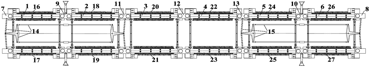
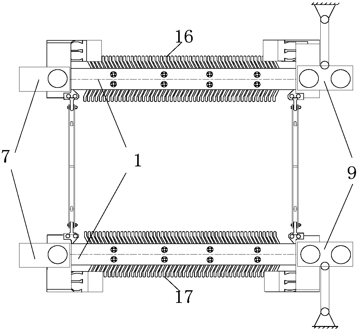
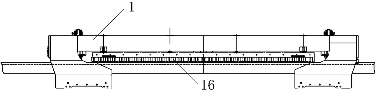
[0036] Such as Figure 1~4 As shown, a running mechanism of a medium-low speed maglev vehicle. The running mechanism includes suspension frames connected in sequence. A linear induction motor stator is suspended on both sides of each suspension frame. There are six suspension frames and a total of twelve linear induction motor stators. and symmetrically distributed on both sides of the running mechanism. The head and end of the running mechanism are provided with a head slide 7 and an end slide 8. Between the head slide 7 and the end slide 8, the first fixed slide 9 and the end slide 8 are sequentially distributed. An intermediate sliding platform 11, a second intermediate sliding platform 12, a third intermediate sliding platform 13 and a second fixed sliding platform 10, and six suspension frames are distributed in sequence and pinned to two adjacent sliding platforms respectively. A first forced guide mechanism 14 is provided between the head end slide table 7 and the first...
Embodiment 2
[0044] Such as Image 6 As shown, the difference between this embodiment and Embodiment 1 is that the way of connecting the four series groups to the vehicle-mounted traction inverter is as follows: all the four series groups are connected in parallel to one vehicle-mounted traction inverter, and the stators of all linear induction motors form three In the form of series four parallel, specifically, all four series groups are connected in parallel to the vehicle-mounted traction inverter 30 . All the other are identical with embodiment 1.
Embodiment 3
[0046] Such as Figure 7 As shown, the difference between this embodiment and Embodiment 1 is that the stators of the linear induction motor on each side of the running mechanism are divided into four groups as follows:
[0047] The linear induction motor stators on each side are first divided into two groups according to the order of arrangement, each group has three linear induction motor stators, and two adjacent linear induction motor stators are selected to be connected in series to form a series group, and the major groups are not connected in series. The linear induction motor stator of the group is connected in series with the non-series linear induction motor stators on the opposite side of the running mechanism to form a series group. The 12 linear induction motor stators form 6 series groups, and the 6 series groups are respectively connected to a vehicle traction inverter. Transformer. The method of connecting the 6 series groups to the vehicle-mounted traction in...
PUM
 Abstract
Description
Claims
Application Information
 - Generate Ideas
- Intellectual Property
- Life Sciences
- Materials
- Tech Scout
- Unparalleled Data Quality
- Higher Quality Content
- 60% Fewer Hallucinations
Browse by: Latest US Patents, China's latest patents, Technical Efficacy Thesaurus, Application Domain, Technology Topic, Popular Technical Reports.
© 2025 PatSnap. All rights reserved.Legal|Privacy policy|Modern Slavery Act Transparency Statement|Sitemap|About US| Contact US: help@patsnap.com