Eureka AIR delivers breakthrough ideas for toughest innovation challenges, trusted by R&D personnel around the world.

Motor rotor device and motor

A technology of motor rotor and rotor core, which is applied in the direction of electromechanical devices, motors, electric components, etc., can solve the problems that the maximum speed of the motor cannot reach a high level, is easy to be damaged, and the robustness of the rotor is deteriorated, so as to reduce the amount of permanent magnets, The effect of reducing dosage and reducing tensile stress

Active Publication Date: 2019-12-06
HUAWEI TECH CO LTD
View PDF14 Cites 6 Cited by
  • Summary
  • Abstract
  • Description
  • Claims
  • Application Information

AI Technical Summary

Problems solved by technology

[0004] Although adding air holes in the rotor will increase the content of reluctance torque, a magnetic bridge will be formed between the air holes or between the air holes and the circumferential surface of the rotor, so the centrifugal force generated by the high-speed rotation of the motor rotor will act on the magnetic bridge. The magnetic bridge on the motor is easily damaged by the tensile stress, which causes the problem of poor rotor robustness, and the maximum speed of the motor cannot reach a higher speed. This is the reason why the maximum speed of electric vehicles is much lower than that of fuel vehicles.

Method used


Image

  • Motor rotor device and motor
  • Motor rotor device and motor
  • Motor rotor device and motor

Examples


Embodiment Construction

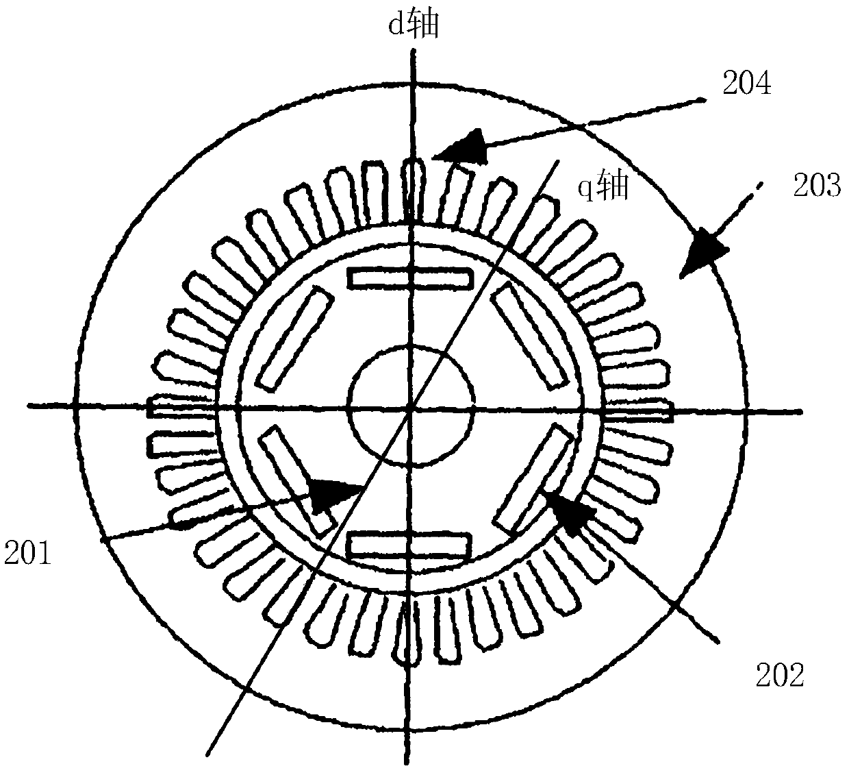
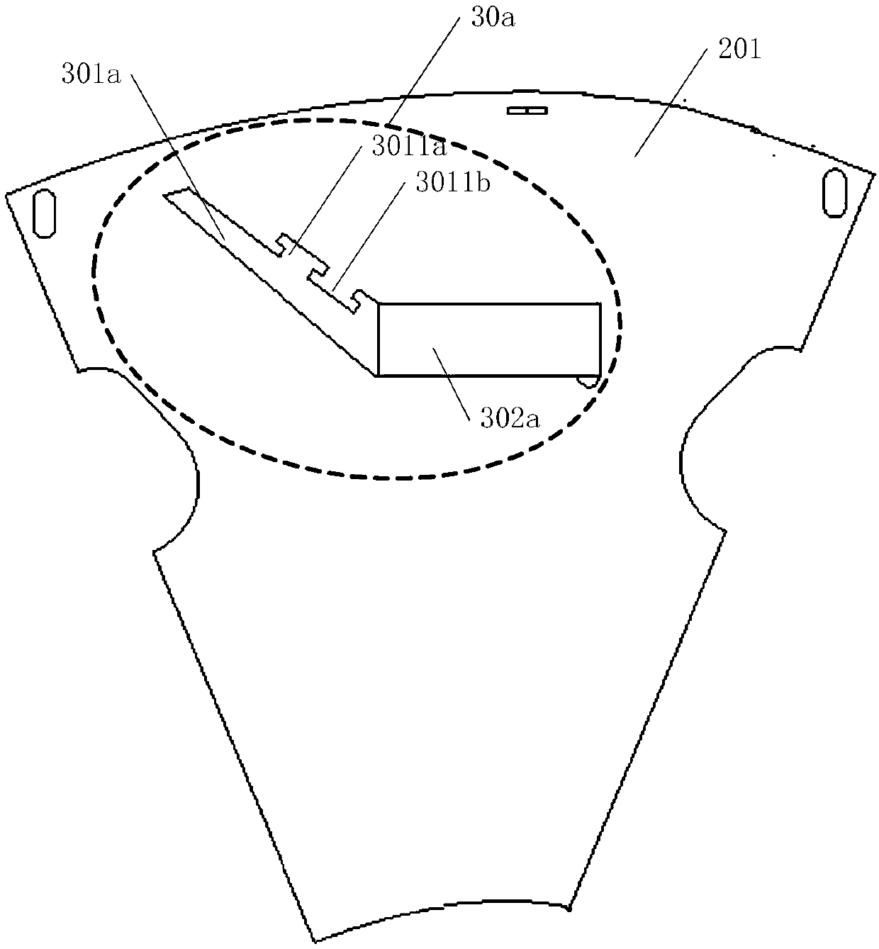
[0042] The present application provides a motor rotor device, which can effectively absorb the centrifugal force generated by the rotor due to high-speed rotation and disperse the effect of the centrifugal force on the magnetic bridge by engaging the adhesive element with the first sub-air groove on the rotor core to form a bearing surface The force ensures the robustness of the rotor at high speed rotation, and can increase the maximum speed of the motor to a certain extent.

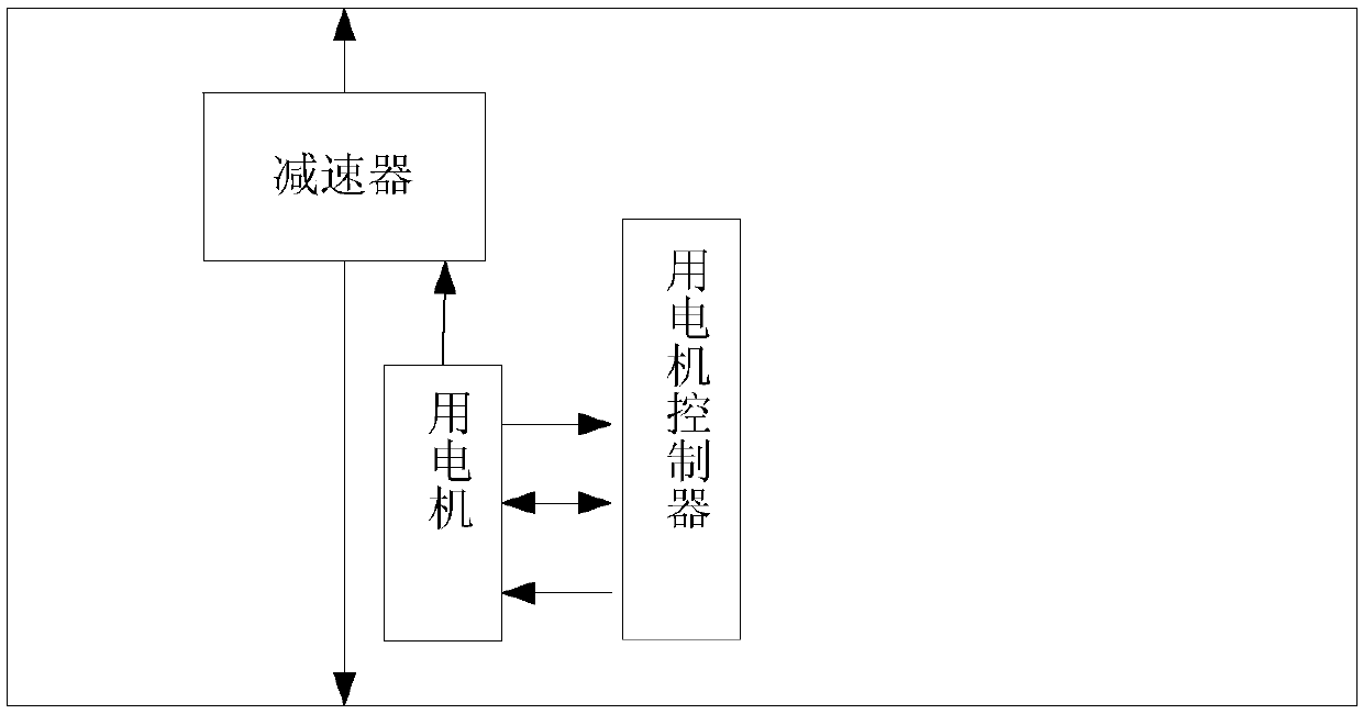
[0043] The increasingly popular electric vehicles satisfy the modern society's life concept of energy saving and environmental protection, so improving the performance of electric vehicles has become the main problem to be solved. figure 1It is a simplified schematic diagram of a motor-driven vehicle, in which the permanent magnet synchronous motor can be used as the main drive motor of an electric vehicle to provide a power source for the electric vehicle to generate driving torque. The motor is driven ...


PUM


Abstract

The present application discloses a motor rotor device. The motor rotor device includes a rotor core and an adhesive element, wherein the adhesive element is fitted to the rotor core; a first sub-airgroove is disposed on the rotor core and includes a first convex tooth and a first groove; the adhesive element includes a second convex tooth and a second groove; the first convex tooth and the second convex tooth match each other; and the first groove and the second groove match each other. The structure where the adhesive element cooperates with the first sub-air groove on the rotor core can effectively absorb the centrifugal tensile force generated by the high-speed rotation of the rotor, significantly reduce the tensile stress on a rotor magnetic bridge, ensures the robustness of the rotor during high-speed rotation, and increases the speed of the motor as much as possible.

Description

technical field [0001] The present application relates to the electromechanical field, in particular to a motor rotor device and a motor. Background technique [0002] As the number of automobiles increases year by year, oil consumption and increasingly severe environmental pressures also increase rapidly, forcing the automobile production industry to follow the development path of energy conservation and environmental protection, so electric vehicles emerge as the times require. The increasingly popular electric vehicles generally use permanent magnet synchronous motors with high power density. The permanent magnet synchronous motor is actually an AC motor. Permanent magnets are installed in the rotor of the motor to generate a permanent rotor magnetic field. Enter three alternating currents with a mutual difference of 120° to generate a rotating magnetic field, and the stator magnetic field interacts with the rotor magnetic field to drive the permanent magnet motor to run....

Claims


Application Information

Patent Timeline
IPC IPC(8): H02K1/27
CPCH02K1/276H02K1/2766H02K1/30
Inventor 吴晓鹏汪一波古拉库·达雅库
Owner HUAWEI TECH CO LTD
Why Eureka
Eureka Blog
Learn More