
Energy feedback-based permanent-magnet speed regulation device

An energy feedback, permanent magnet speed regulation technology, which is applied to electromechanical devices, permanent magnet clutches/brakes, asynchronous induction clutches/brakes, etc. Speed ​​system transmission shaft wear, large footprint and other issues, to achieve the effect of solving the large footprint

Pending Publication Date: 2018-08-28
DALIAN JIAOTONG UNIVERSITY
View PDF1 Cites 0 Cited by
  • Summary
  • Abstract
  • Description
  • Claims
  • Application Information

AI Technical Summary

Problems solved by technology

[0002] Chinese patent CN201710262226.2 proposes a current-adjustable permanent magnet speed control device, which solves the two long-standing problems of the existing permanent magnet speed control device, such as large slip heat generation and easy wear of the transmission shaft of the speed control system.
[0003] (1) Due to the use of brushes and slip rings to adjust the induced current inside the rotor for rotor speed regulation, the axial length of the entire speed regulating device is long and the floor space is large;
[0004] (2) The brush and the slip ring are a combination of dynamic and static structures. Not only will the brush be replaced regularly due to wear and tear, but also if the brush and the slip ring are not properly matched, discharge and ignition will easily occur, resulting in slip ring or brush failure. premature damage of
[0005] (3) There are two methods for its speed regulation: ① adjust the induced current in the coil winding through an external variable resistance box, that is, the slip power is consumed in the form of heat through the resistance in the resistance box, that is to say, the slip The power cannot be recovered; ②The current is fed back to the grid through the inverter for further energy saving; due to the high voltage of the grid, this method requires a transformer to boost the voltage before it can be fed back to the grid. This kind of transformer is not only expensive, but also And it occupies a large area

Method used


Image

  • Energy feedback-based permanent-magnet speed regulation device
  • Energy feedback-based permanent-magnet speed regulation device
  • Energy feedback-based permanent-magnet speed regulation device

Examples


Embodiment Construction

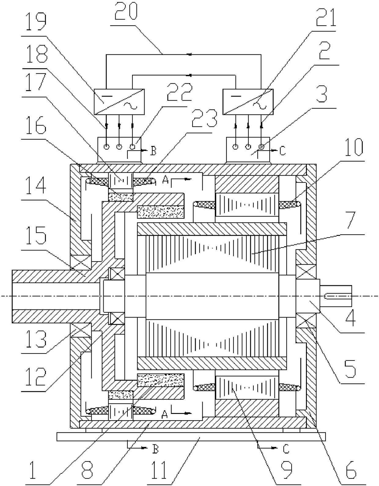
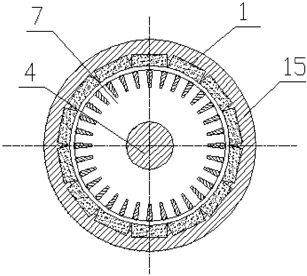
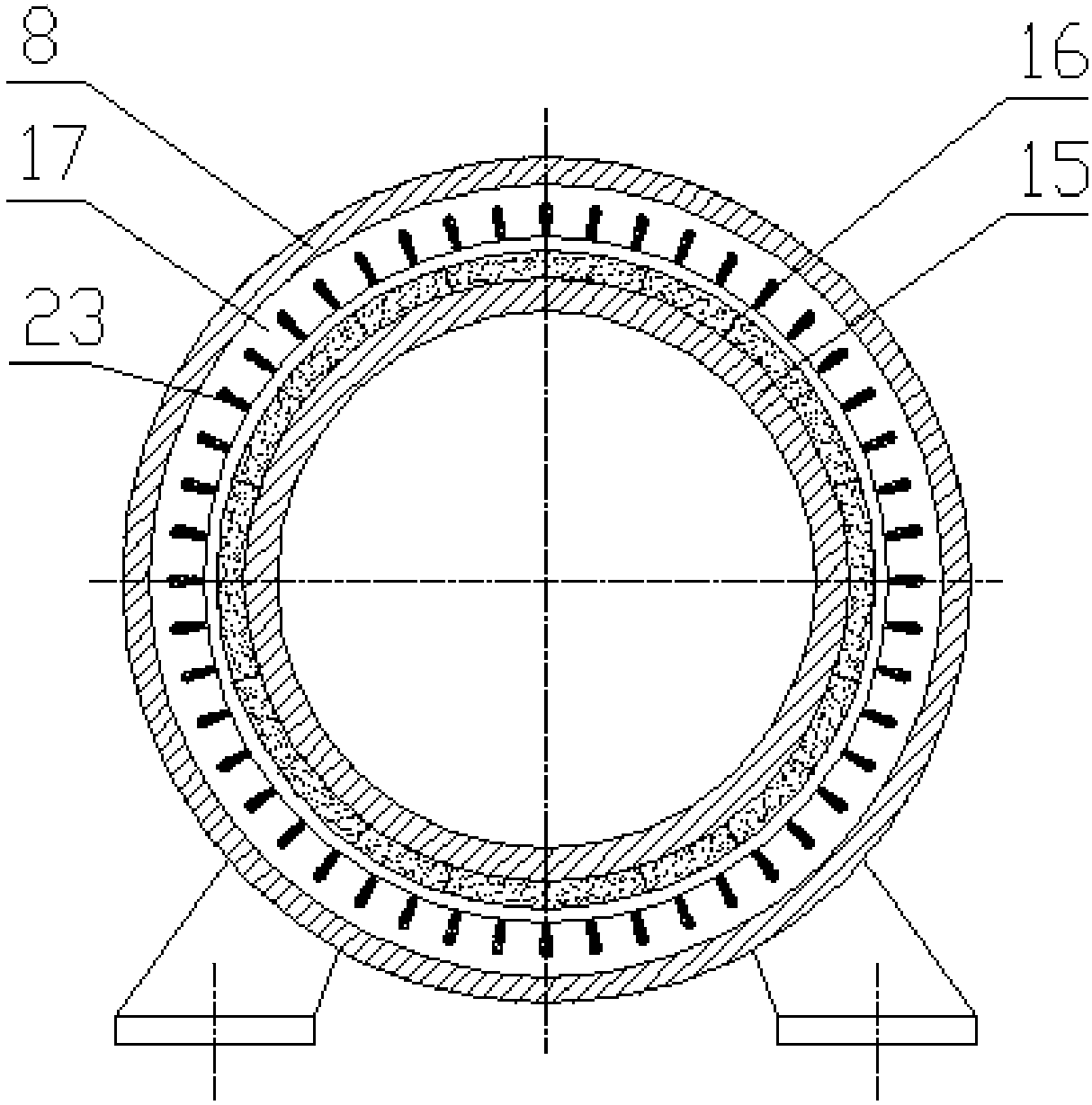
[0027] The present invention will be further described below in conjunction with accompanying drawing, as Figure 1-4 As shown, based on the energy feedback type permanent magnet speed control device, it includes an outer rotor assembly, an inner rotor assembly, an energy feedback device assembly and a base assembly; the outer rotor assembly includes permanent magnets I1, permanent magnets II16 , embedded bearing 12 and power input shaft 15; described inner rotor assembly includes inner rotor coil winding 7 and power output shaft 4; described energy feedback device assembly includes stator yoke iron I9, stator coil I10, shell body 8, outlet box 3, stator winding outlet 2, inverter I21, cable 20, inverter II19, stator winding inlet 18 and inlet box 22; the base assembly includes a bottom plate 11, a left end bearing end Cover 14, left end bearing 13, right end bearing end cover 6 and right end bearing 5.

[0028] The permanent magnet I1 is installed on the largest inner surfac...


PUM


Abstract

The invention discloses an energy feedback-based permanent-magnet speed regulation device. The energy feedback-based permanent-magnet speed regulation device comprises an outer rotor assembly, an inner rotor assembly, an energy feedback device assembly and an engine base assembly. According to an electromagnetic induction method, an induced potential in a rotor loop is adjusted, current and electromagnetic torque in the rotor loop are changed, and the adjustment of a rotational speed of a rotor is further achieved. By the energy feedback-based permanent-magnet speed regulation device, a sliding ring and electric brush structure is eliminated, the problems of large occupancy area and high fault ratio of the electric brush and sliding ring structure in the prior art are fundamentally solved.A slip power is recycled in an electric power mode, at the moment, an input power of a power input shaft can be reduced, and the reduced part is the slip power which is recycled; and more energy is saved compared with the prior art; the problem that a high-voltage frequency converter which is high in cost and is easy to damage shall be employed by a traditional high-voltage motor speed regulationdevice is solved; and the full-power requirement of the motor can be met by employing an inverter with relatively small capacity.

Description

technical field [0001] The invention relates to a permanent magnet speed regulating device, in particular to an energy feedback-based permanent magnet speed regulating device. Background technique [0002] Chinese patent CN201710262226.2 proposes a current-adjustable permanent magnet speed control device, which solves the two long-standing problems of the existing permanent magnet speed control device, such as large slip heat generation and easy wear of the transmission shaft of the speed control system. But the device has the following problems: [0003] (1) Due to the use of brushes and slip rings to adjust the induced current inside the rotor for rotor speed regulation, the axial length of the entire speed regulating device is long and the floor space is large; [0004] (2) The brush and the slip ring are a combination of dynamic and static structures. Not only will the brush be replaced regularly due to wear and tear, but also if the brush and the slip ring are not prop...

Claims


Application Information

Patent Timeline
IPC IPC(8): H02K49/10H02K49/02H02K5/16
CPCH02K5/161H02K49/02H02K49/106
Inventor 葛研军杨均悦
Owner DALIAN JIAOTONG UNIVERSITY
Learn More