
Seafloor sediment reflectivity measuring device and method

A measuring device and reflectivity technology, applied in the field of spectral measurement, can solve the problems of increased probability of failure, high price of spectral probes, different measurement errors, etc., to achieve the effect of low manufacturing and operating costs

Active Publication Date: 2018-08-28
SOUTH CHINA SEA INST OF OCEANOLOGY - CHINESE ACAD OF SCI
View PDF4 Cites 1 Cited by
  • Summary
  • Abstract
  • Description
  • Claims
  • Application Information

AI Technical Summary

Problems solved by technology

[0010] Although the above-mentioned underwater spectrometer can measure the reflectivity of the bottom of the seabed, because it uses two spectral probes, on the one hand, the price of the spectral probes is high, resulting in a high cost of the entire device, and the probability of failure will also increase exponentially ; On the other hand, there will be differences in the spectral data collected by the two spectral probes, even if it can be corrected through calibration, but in the long-term field work, the attenuation of optical equipment and the influence of temperature have individual differences in physique, resulting in DN1 and DN2. measurement accuracy drift, which in turn causes R 未 The calculation produces errors, which affect the measurement accuracy of reflectivity
[0011] In addition, the optical probe of the underwater spectrometer and the white board used as a reference may need to be immersed in seawater for several days or even a year for long-term series of measurements, and long-term immersion in seawater is vulnerable to organisms and organic substances (such as oil) in the water. species) and inorganic substances (such as sediment), and optical radiation measurement is very sensitive to this pollution, and the measurement error of each window is also different after being polluted.
In summary, the measurement of dual probes still has its own limitations in terms of equipment cost and accuracy.

Method used


Image

  • Seafloor sediment reflectivity measuring device and method
  • Seafloor sediment reflectivity measuring device and method
  • Seafloor sediment reflectivity measuring device and method

Examples


Embodiment

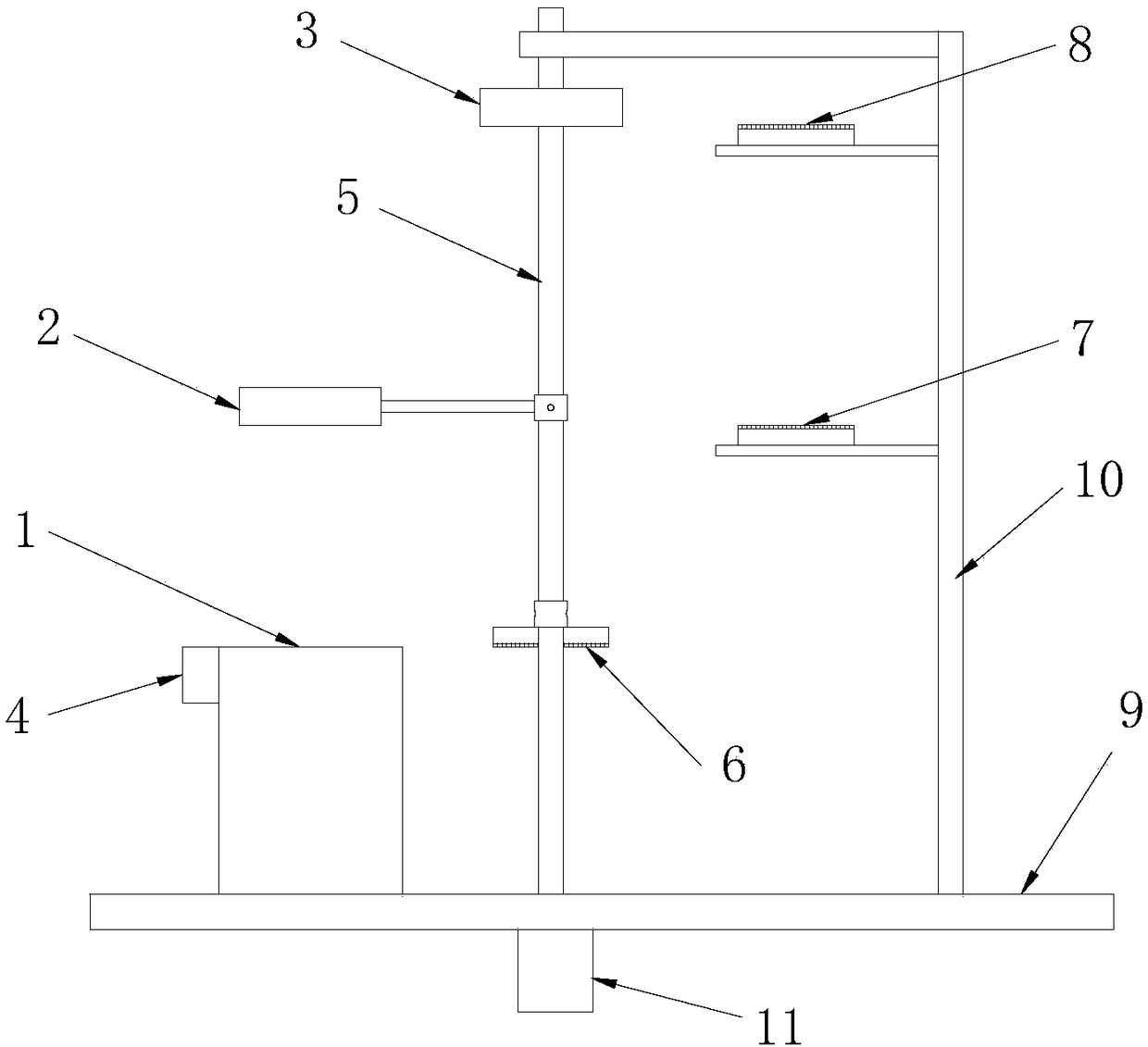
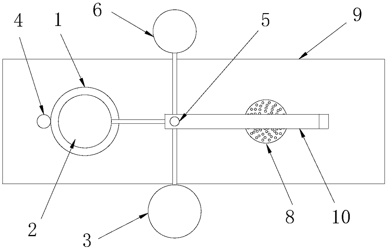
[0038] Such as figure 1 with 2 As shown, a device for measuring the reflectivity of the bottom of the seabed includes a spectrum probe 1, a first whiteboard 2, a second whiteboard 3, a rangefinder 4, a rotating shaft 5, a movable brush 6, a first fixed brush 7, and a second fixed brush 8. Base 9, L-shaped bracket 10 and drive motor 11. As for other components of the device, such as: spectrum analyzer, processor, display, power supply, sealing components, depth probe and camera, all can be arranged according to actual needs, which are all conventional technologies, and will not be repeated here.

[0039]The base 9 is used as the bearing platform of the measuring device, the spectrum probe 1 and the rangefinder 4 are installed on the upper surface of the base 9, the rangefinder 4 can be fixed on the spectrum probe 1 or the base 9, and the driving motor 11 is installed on the base 9. On the lower surface, the upper end of the L-shaped bracket 10 is rotationally connected to th...


PUM


Abstract

The invention discloses a seafloor sediment reflectivity measuring device and method. The seafloor sediment reflectivity measuring device comprises a spectrum probe, a first whiteboard, a second whiteboard, a range finder and a rotating shaft, wherein the reflectivity of the first whiteboard and the second whiteboard is known, and the first whiteboard and the second whiteboard are connected onto the rotating shaft with a spacing along the axial direction of the rotating shaft and is staggered from each other along the radial direction of the rotating shaft; the spectral probe is used for acquiring spectral data of the first whiteboard, the second whiteboard and seafloor sediments; the range finder is used for acquiring data about the space between the first whiteboard and the seafloor sediments; the rotating shaft is used for driving the first whiteboard and the second whiteboard to rotate to be in front of the spectral probe sequentially. According to the invention, the seafloor sediment reflectivity can be measured with only one spectral probe, so as to further monitor the health status of seaweed and coral, the production and running cost of the measuring device are low, and theproblem of measurement deviation caused by different spectral probes is solved to some extent.

Description

technical field [0001] The invention relates to the technical field of spectrum measurement, in particular to a device and method for measuring the reflectance of seabed bottom. Background technique [0002] When the sunlight is incident on the seawater interface, part of the sunlight is directly reflected by the surface of the seawater into the air, and the other part of the sunlight enters the seawater. Since seawater is generally composed of pure seawater, phytoplankton, suspended sediment, and colored dissolved organic matter, sunlight entering seawater is absorbed and scattered by seawater, and part of the scattered light penetrates the sea-air interface, carrying seawater components. The information passes through the atmosphere and is received by relevant satellites. Therefore, by studying the optical signals of satellites, the information of seawater components can be retrieved, and the relevant information of the ocean can be obtained. [0003] However, for near-s...

Claims


Application Information

Patent Timeline
IPC IPC(8): G01N21/55G01N21/15
CPCG01N21/15G01N21/55G01N2021/152G01N21/255G01N21/276G01N2021/1793G01N2201/0218G01N2201/0616
Inventor 许占堂赵俊杨跃忠李彩周雯曾凯曹文熙
Owner SOUTH CHINA SEA INST OF OCEANOLOGY - CHINESE ACAD OF SCI
Learn More