
High-concentration paper pulp conveying device

A conveying device and high-concentration technology, applied in pipeline systems, mechanical equipment, gas/liquid distribution and storage, etc., can solve problems such as cumbersome operation, limited use of pipelines, complex pump body structure, etc., and improve structural stability , to facilitate subsequent cleaning, to ensure the effect of pulp concentration

Inactive Publication Date: 2018-08-28
江苏妙卫纸业有限公司
View PDF5 Cites 0 Cited by
  • Summary
  • Abstract
  • Description
  • Claims
  • Application Information

AI Technical Summary

Problems solved by technology

[0002] Pulp is a fibrous substance made from plant fibers through different processing methods. It is the basic raw material of the paper industry. It can be divided into mechanical pulp, chemical pulp and chemical mechanical pulp according to the processing method. In the production process, some industrial pipelines are often used to transport pulp, and the use of these pipelines is limited. When transporting high-concentration pulp, it is very easy to cause pipeline blockage, which seriously affects the efficiency and economy of industrial production. To prevent blockage, Manufacturers will specifically use some pump bodies that are convenient for transportation, but this type of pump body is complex in structure, high in cost, and easy to wear inside. Some factories will be equipped with suitable transportation equipment to separate high-concentration pulp. Transportation, but this kind of transportation equipment does not consider the characteristics of pulp, and it is very easy to cause solidification and other phenomena during transportation, and the process of pulp export is more cumbersome, which seriously affects production efficiency

Method used


Image

  • High-concentration paper pulp conveying device
  • High-concentration paper pulp conveying device
  • High-concentration paper pulp conveying device

Examples


Embodiment Construction

[0014] The following will clearly and completely describe the technical solutions in the embodiments of the present invention with reference to the accompanying drawings in the embodiments of the present invention. Obviously, the described embodiments are only some, not all, embodiments of the present invention. Based on the embodiments of the present invention, all other embodiments obtained by persons of ordinary skill in the art without making creative efforts belong to the protection scope of the present invention.

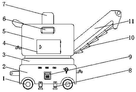
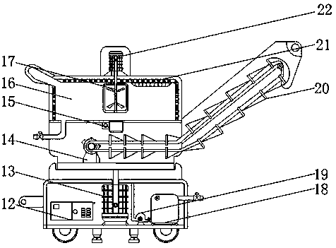
[0015] see Figure 1-3 , an embodiment provided by the present invention: a high-concentration pulp conveying device, including a base 2, a main box body 5 and a storage cavity 16, and a detachable leg 8 is installed on the bottom of the base 2, which can increase the protection of the device Supporting force, improving structural stability, the bottom of the base 2 on both sides of the detachable leg 8 is equipped with walking wheels 1, so that the device has...


PUM


Abstract

The invention discloses a high-concentration paper pulp conveying device. The device comprises a base, a main box body and a storage cavity, and a detachable supporting leg is arranged at the bottom of the base; walking wheels are installed at the bottoms of the base on the two sides of the detachable supporting leg, a rotating motor is arranged in the base, and a rotating table is arranged at thetop of the base; a conveying shell is arranged on the surface of one side of the main box body, and a feeding hopper is arranged on the surface of the other side of the main box body; a protective shell is arranged at the top of the main box body, a stirring motor is arranged in the protective shell, and a stirrer is arranged inside the storage cavity; and a servo motor is installed inside the main box body below the storage cavity, and a transmission chain is arranged on the surface of the servo motor. According to the high-concentration paper pulp conveying device, a series of structures are arranged, in the using process, the high-concentration paper pulp can be directionally conveyed, the performance stability of paper pulp can be guaranteed, and the conveying quality can be improved.

Description

technical field [0001] The invention relates to the technical field of paper product production, in particular to a high-concentration pulp conveying device. Background technique [0002] Pulp is a fibrous substance made from plant fibers through different processing methods. It is the basic raw material of the paper industry. It can be divided into mechanical pulp, chemical pulp and chemical mechanical pulp according to the processing method. In the production process, some industrial pipelines are often used to transport pulp, and the use of these pipelines is limited. When transporting high-concentration pulp, it is very easy to cause pipeline blockage, which seriously affects the efficiency and economy of industrial production. To prevent blockage, Manufacturers will specifically use some pump bodies that are convenient for transportation, but this type of pump body is complex in structure, high in cost, and easy to wear inside. Some factories will be equipped with suita...

Claims


Application Information

Patent Timeline
Patent Type & Authority Applications(China)
IPC IPC(8): F17D1/08F17D5/00
CPCF17D1/08F17D5/00
Inventor 陆泳东
Owner 江苏妙卫纸业有限公司
Learn More