Automatic feeding equipment

A technology of equipment and main control equipment, applied in the direction of conveyor objects, transportation and packaging, etc., can solve the problems of high cost and complex technology, and achieve the effect of simple structure and automation

Active Publication Date: 2018-08-28
SHANGHAI JINDONGTANG TECH CO LTD
View PDF11 Cites 2 Cited by
  • Summary
  • Abstract
  • Description
  • Claims
  • Application Information

AI Technical Summary

Problems solved by technology

Although the above two methods can effectively solve the problem of material position deviation, the cost is high and the technology is complicated

Method used


Image

  • Automatic feeding equipment
  • Automatic feeding equipment
  • Automatic feeding equipment

Examples


Embodiment Construction

[0025] In order to make the object, technical solution and advantages of the present invention clearer, various embodiments of the present invention will be described in detail below in conjunction with the accompanying drawings. However, those of ordinary skill in the art can understand that, in each implementation manner of the present invention, many technical details are provided for readers to better understand the present application. However, even without these technical details and various changes and modifications based on the following implementation modes, the technical solution claimed in this application can also be realized.

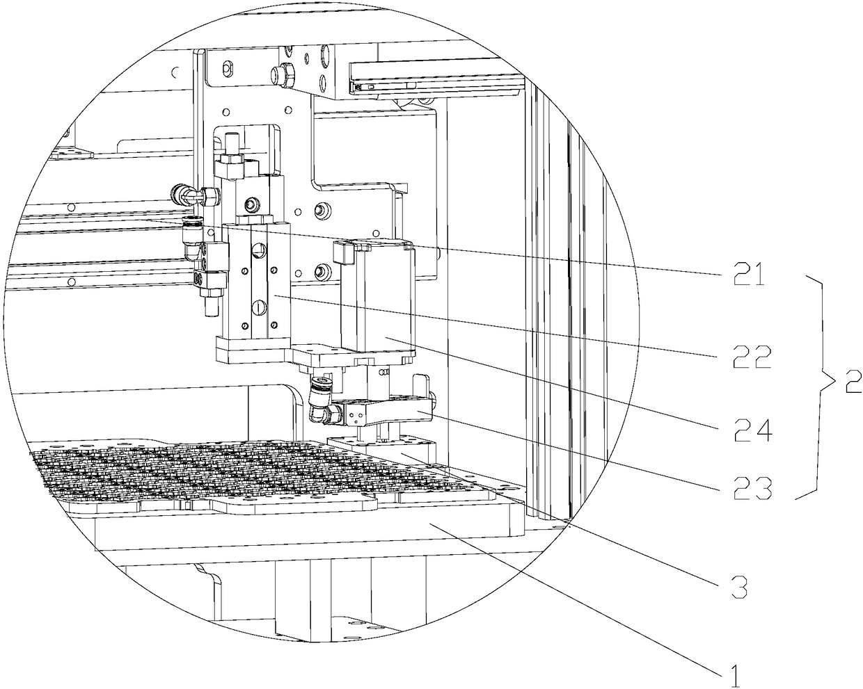
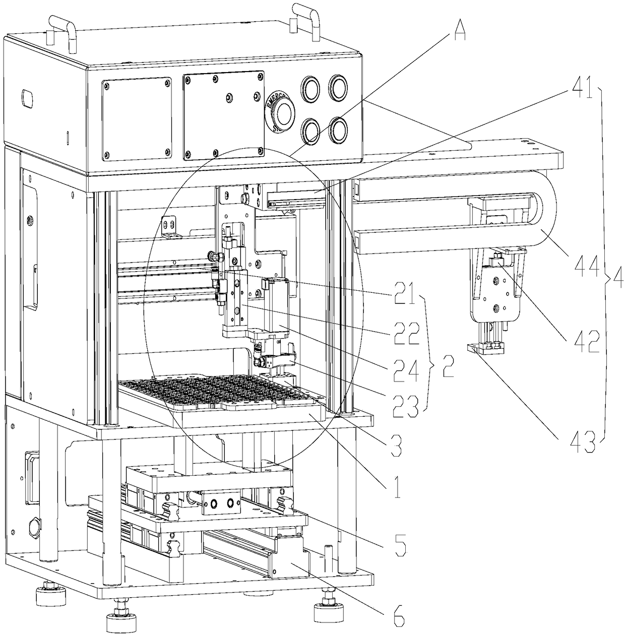
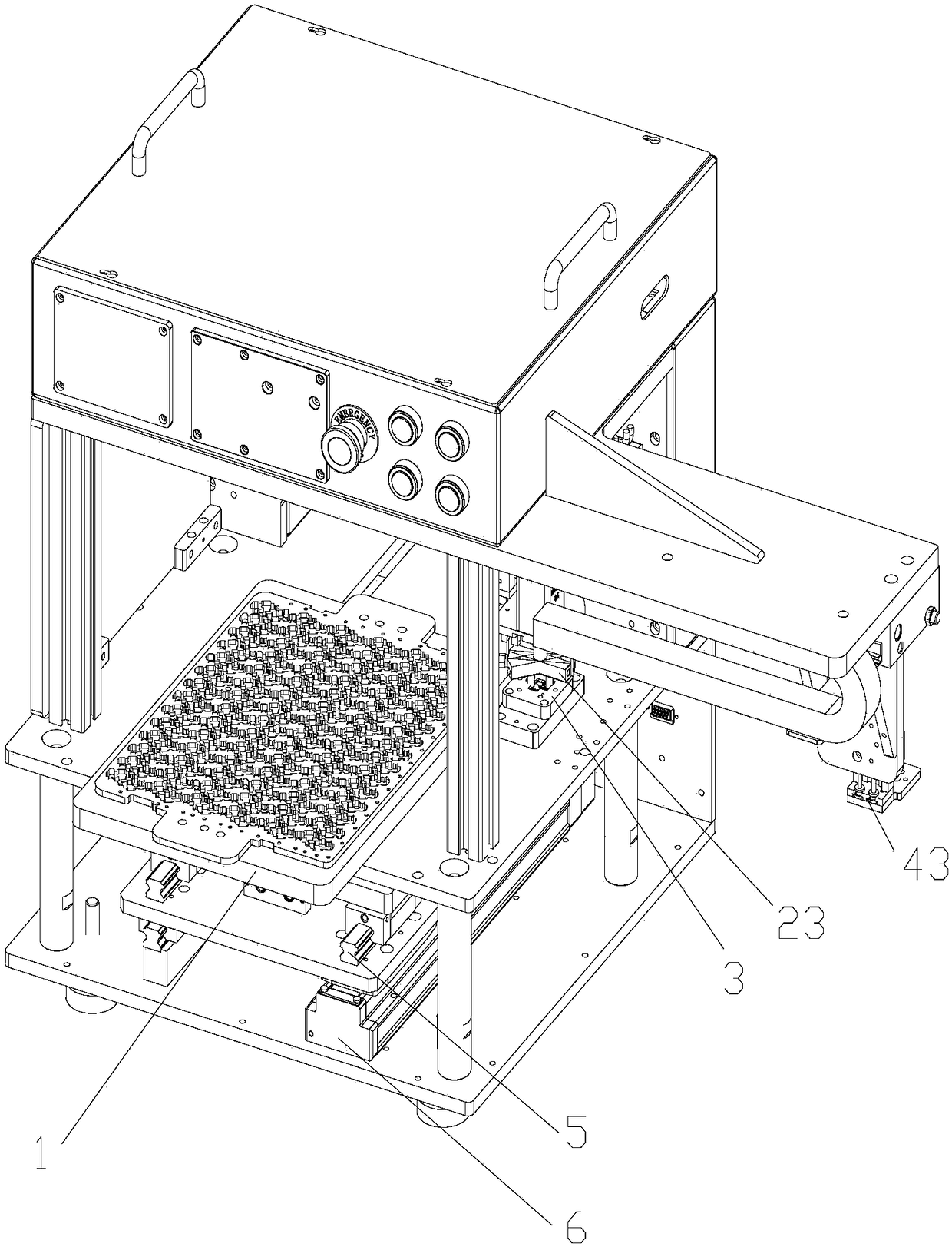
[0026] The first embodiment of the present invention relates to an automatic feeding equipment, such as Figure 1-4 As shown, it includes: a loading tray 1, a correction mechanism 2, a correction block 3, a feeding mechanism 4, and a main control device (not shown in the figure), wherein the main control device is electrically connected to ...


PUM


Abstract

The invention relates to the field of automation equipment and discloses automatic feeding equipment. The automatic feeding equipment comprises a carrying tray, a rectifying mechanism, a rectifying block, a feeding mechanism and a master control device, wherein the master control device is electrically connected with the rectifying mechanism and the feeding mechanism; the rectifying block is provided with a rectifying groove; the rectifying groove corresponds to a material in shape and is used for allowing the material to be smoothly embedded in the rectifying groove; the rectifying mechanismcomprises a rectifying electric cylinder, a rectifying cylinder and a rectifying suction nozzle; the feeding mechanism comprises a feeding electric cylinder, a feeding cylinder and a feeding suction nozzle. The automatic feeding equipment provided by the embodiment of the invention achieves rectifying and feeding automation and achieves the rectifying effect through cooperation of the rectifying mechanism and the rectifying block. Compared with artificial visual rectifying and computer visual rectifying methods in the prior art, the automatic feeding equipment has the advantage of being simplein structure,

Description

technical field [0001] The invention relates to the field of automation equipment, in particular to an automatic feeding equipment. Background technique [0002] At present, in the field of automated production, such as in the FPC (Flexible Printed Circuit, flexible circuit board) loading and testing process, it is necessary to transfer the FPC material to the testing equipment through the loading equipment, and then the testing equipment performs subsequent testing operations on it. [0003] In the prior art, there have been some automatic feeding equipment to replace manual feeding to achieve the purpose of improving production efficiency and reducing labor production costs, most of which include linear electric cylinders and The tray is set on the electric cylinder and driven by the electric cylinder to move along a straight line until the material is delivered to the testing equipment. During the process of placing materials, there will inevitably be deviations between ...

Claims


Application Information

Patent Timeline
Patent Type & Authority Applications(China)
IPC IPC(8): B65G47/91
CPCB65G47/912
Inventor 王文秀袁琮
Owner SHANGHAI JINDONGTANG TECH CO LTD
Why Eureka
Try Eureka