Mechanical iron plate surface double-layer synchronous polishing equipment
An iron plate, double-layer technology, applied in the direction of grinding/polishing equipment, machine tools for surface polishing, metal processing equipment, etc., can solve the problems of slow polishing speed, time-consuming and laborious, etc.
- Summary
- Abstract
- Description
- Claims
- Application Information
AI Technical Summary
Problems solved by technology
Method used
Image

Examples
Embodiment 1
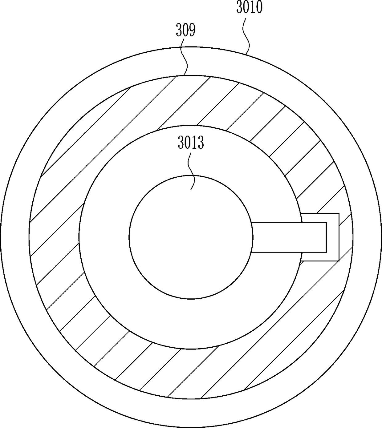
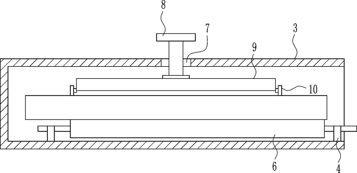
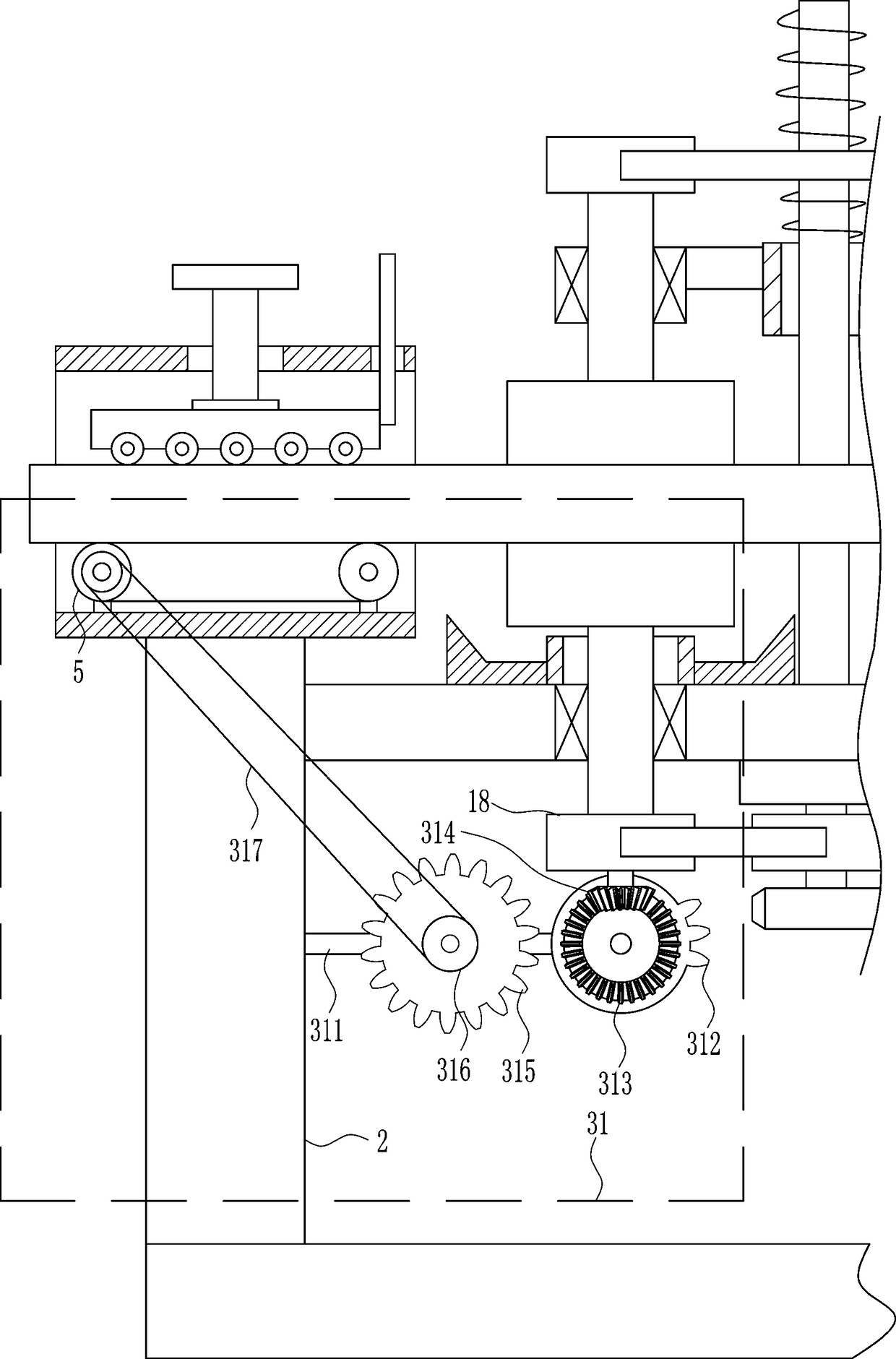
[0032] A kind of double-layer synchronous polishing equipment on the surface of mechanical iron plate, such as Figure 1-9 As shown, it includes a base plate 1, a support plate 2, an N-shaped frame 3, a first connecting block 4, a first runner 5, a conveyor belt 6, a screw 8, a second connecting block 9, a roller 10, a guide rod 12, and a mounting plate 13. The first bearing seat 14, the first rotating rod 15, the first polishing wheel 16, the motor 17, the second rotating wheel 18 and the first transmission bar 19, the left and right sides of the bottom plate 1 are connected with the support plate 2, the support plate 2 The upper ends are connected with N-shaped frames 3, and the upper, left and right sides of the lower walls of the two N-shaped frames 3 are connected with first connecting blocks 4, and the upper sides of the first connecting blocks 4 are connected with first runners 5. A conveyor belt 6 is connected between the runners 5, a threaded hole 7 is provided in the...
Embodiment 2
[0034] A kind of double-layer synchronous polishing equipment on the surface of mechanical iron plate, such as Figure 1-9 As shown, it includes a base plate 1, a support plate 2, an N-shaped frame 3, a first connecting block 4, a first runner 5, a conveyor belt 6, a screw 8, a second connecting block 9, a roller 10, a guide rod 12, and a mounting plate 13. The first bearing seat 14, the first rotating rod 15, the first polishing wheel 16, the motor 17, the second rotating wheel 18 and the first transmission bar 19, the left and right sides of the bottom plate 1 are connected with the support plate 2, the support plate 2 The upper ends are connected with N-shaped frames 3, and the upper, left and right sides of the lower walls of the two N-shaped frames 3 are connected with first connecting blocks 4, and the upper sides of the first connecting blocks 4 are connected with first runners 5. A conveyor belt 6 is connected between the runners 5, a threaded hole 7 is provided in the...
Embodiment 3
[0037] A kind of double-layer synchronous polishing equipment on the surface of mechanical iron plate, such as Figure 1-9 As shown, it includes a base plate 1, a support plate 2, an N-shaped frame 3, a first connecting block 4, a first runner 5, a conveyor belt 6, a screw 8, a second connecting block 9, a roller 10, a guide rod 12, and a mounting plate 13. The first bearing seat 14, the first rotating rod 15, the first polishing wheel 16, the motor 17, the second rotating wheel 18 and the first transmission bar 19, the left and right sides of the bottom plate 1 are connected with the support plate 2, the support plate 2 The upper ends are connected with N-shaped frames 3, and the upper, left and right sides of the lower walls of the two N-shaped frames 3 are connected with first connecting blocks 4, and the upper sides of the first connecting blocks 4 are connected with first runners 5. A conveyor belt 6 is connected between the runners 5, a threaded hole 7 is provided in the...
PUM
 Abstract
Description
Claims
Application Information
 - R&D
- Intellectual Property
- Life Sciences
- Materials
- Tech Scout
- Unparalleled Data Quality
- Higher Quality Content
- 60% Fewer Hallucinations
Browse by: Latest US Patents, China's latest patents, Technical Efficacy Thesaurus, Application Domain, Technology Topic, Popular Technical Reports.
© 2025 PatSnap. All rights reserved.Legal|Privacy policy|Modern Slavery Act Transparency Statement|Sitemap|About US| Contact US: help@patsnap.com