
Brake control system of centrifugal cylinder for dialyzer and centrifugal device for dialyzer

A brake control and centrifugal device technology, applied in the direction of centrifuges, etc., can solve problems such as mechanical wear, centrifugal cylinder vibration, and complex structure, and achieve the effect of simple structure, avoiding mechanical friction, and ensuring centrifugal effect

Active Publication Date: 2021-02-26
MAIDER MEDICAL IND EQUIP
View PDF11 Cites 0 Cited by
  • Summary
  • Abstract
  • Description
  • Claims
  • Application Information

AI Technical Summary

Problems solved by technology

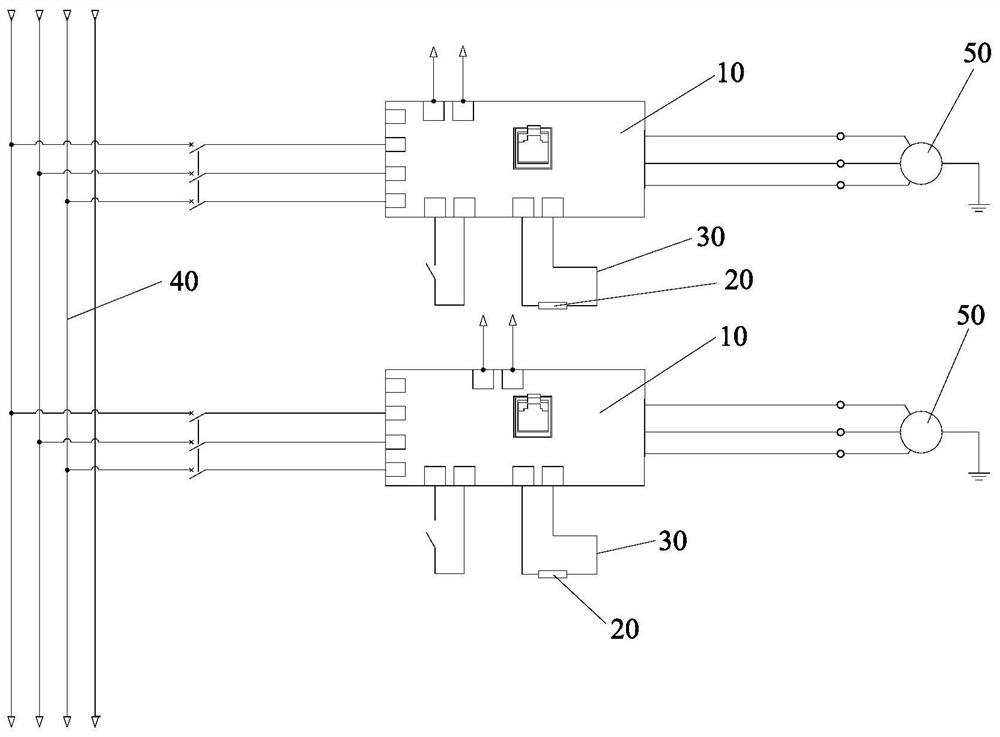
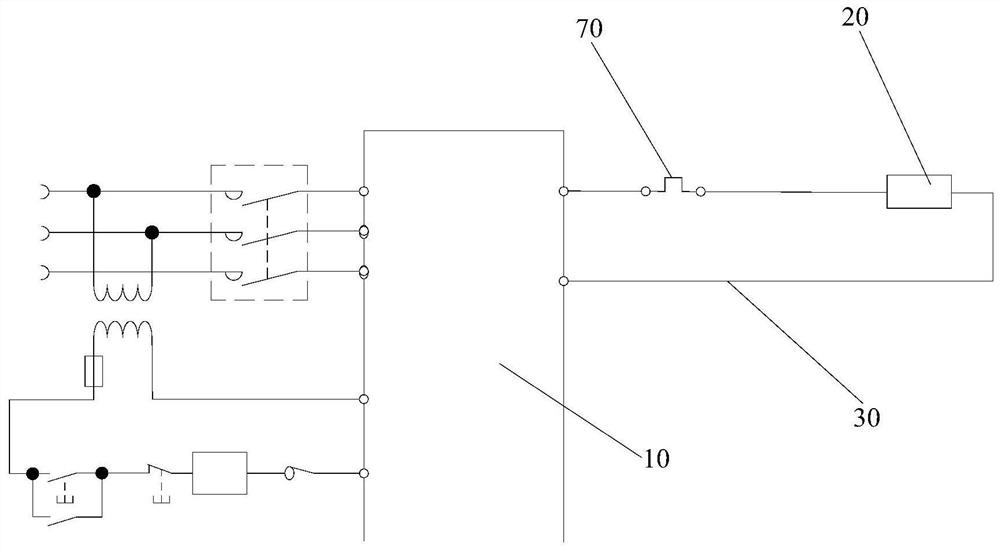
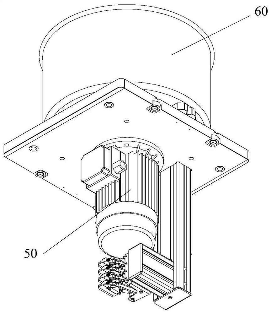
[0006] The main purpose of the present invention is to provide a brake control system for a centrifugal cylinder for a dialyzer and a centrifugal device for a dialyzer, so as to solve the problem that the structure of the mechanical brake device in the prior art is complicated, mechanical wear is prone to occur, and the centrifugal cylinder will shake during the braking process. , the problem of affecting the centrifugal effect of the glue

Method used


Image

  • Brake control system of centrifugal cylinder for dialyzer and centrifugal device for dialyzer
  • Brake control system of centrifugal cylinder for dialyzer and centrifugal device for dialyzer
  • Brake control system of centrifugal cylinder for dialyzer and centrifugal device for dialyzer

Examples


Embodiment Construction

[0026] It should be noted that, in the case of no conflict, the embodiments in the present application and the features in the embodiments can be combined with each other. The present invention will be described in detail below with reference to the accompanying drawings and examples.

[0027] It should be pointed out that the following detailed description is exemplary and intended to provide further explanation to the present application. Unless defined otherwise, all technical and scientific terms used herein have the same meaning as commonly understood by one of ordinary skill in the art to which this application belongs.

[0028] The following will clearly and completely describe the technical solutions in the embodiments of the present invention with reference to the accompanying drawings in the embodiments of the present invention. Obviously, the described embodiments are only some, not all, embodiments of the present invention. The following description of at least on...


PUM


Abstract

The invention provides a brake control system for a centrifugation barrel for a dialyzer and a centrifugation device for the dialyzer. The brake control system comprises control sub-systems. Each control sub-system comprises a frequency converter and an energy consumption brake module, wherein each frequency converter is electrically connected with a motor of the centrifugation barrel, and each energy consumption brake module is connected with the corresponding frequency converter. Each energy consumption brake module is used for consuming and / or shifting energy generated in the brake processof the corresponding motor. By means of the brake control system, the problems that in the prior art, a mechanical brake device is complex in structure and prone to mechanical abrasion, in addition, in the brake process, a centrifugation barrel is likely to shake, and the centrifugation effect of glue liquor is affected can be solved.

Description

technical field [0001] The invention relates to the technical field of auxiliary production equipment for medical appliances, in particular to a brake control system for a centrifugal cylinder for a dialyzer and a centrifugal device for a dialyzer. Background technique [0002] Dialyzer is a kind of semi-permeable membrane principle, so that blood and dialysate flow in opposite directions on both sides of the dialysis membrane. With the help of solute gradient, osmotic gradient and water pressure gradient on both sides of the membrane, toxins and retained water in the body are removed. A medical device that replenishes the substances needed in the body. [0003] The dialyzer mainly consists of a shell and a fiber bundle installed in the shell. During the assembly process of the dialyzer, after installing the fiber bundle into the shell of the dialyzer, it is necessary to inject glue into the shell and centrifuge the glue so that the glue is in the gap between the two ends o...

Claims


Application Information

Patent Timeline
Patent Type & Authority Patents(China)
IPC IPC(8): B04B13/00B04B15/02
CPCB04B13/00B04B15/02
Inventor 赵思彬
Owner MAIDER MEDICAL IND EQUIP
Learn More