Driven centrifugal unit, manufacturing method and using method of driven centrifugal unit and solid-liquid separation equipment with driven centrifugal unit
A technology of solid-liquid separation and centrifugal cover, applied in the field of centrifuges, can solve the problems of complex manufacturing process, inconvenient maintenance, large noise and vibration, etc.
- Summary
- Abstract
- Description
- Claims
- Application Information
AI Technical Summary
Problems solved by technology
Method used
Image
Examples
Embodiment 1
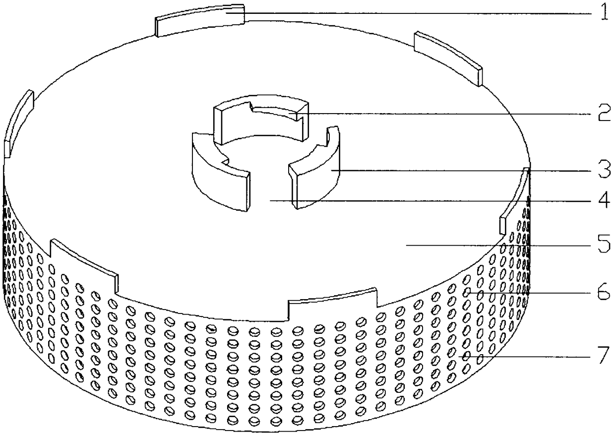
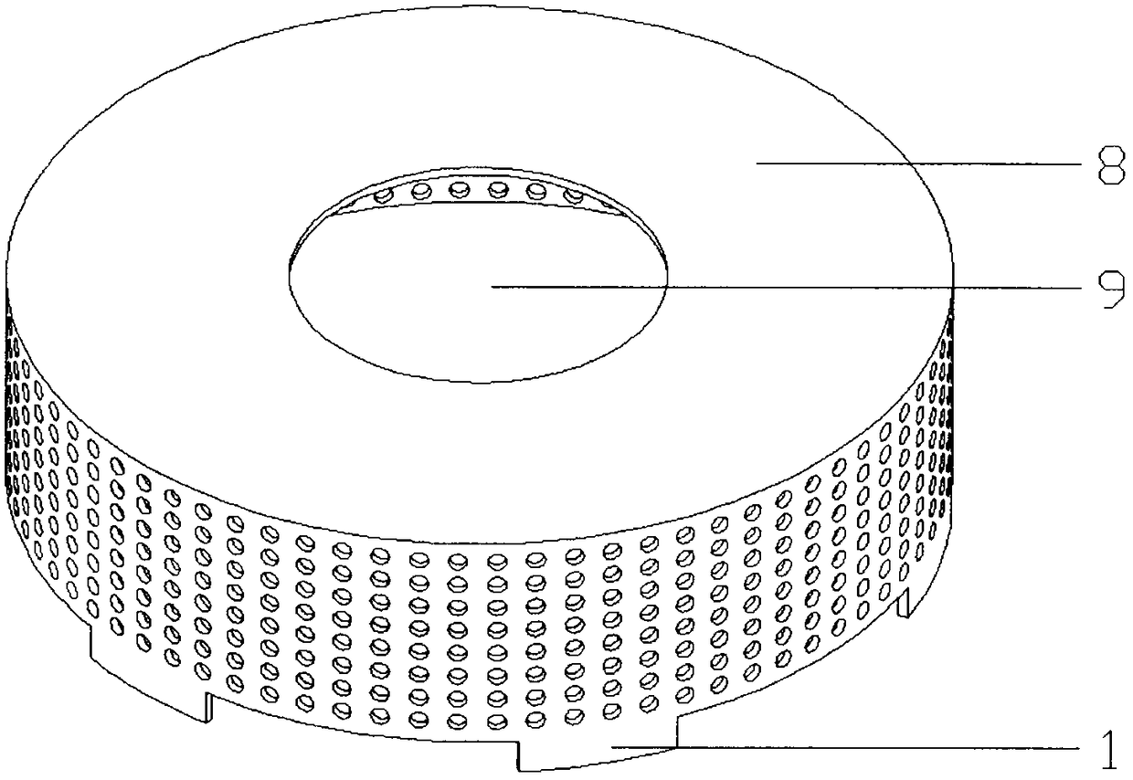
[0209] This embodiment is a driven centrifugal unit with a lock cylinder (3), and its structural schematic diagram is shown in Fig. 1 (comprising Figure 1A and Figure 1B ).
[0210] As shown in Figure 1, according to Figure 8 The method (7) in turn passes through the following steps:
[0211] The first step: select the steel plate;
[0212] Step 2: Stamping and forming the main body with the centrifugal cover (8), feeding hole (9), card-shaped protrusion (1), centrifugal drum (7) and the centrifugal through hole (6) formed by punching on it Part A embryo body (i.e. the first metal part with centrifuge lid and centrifuge bowl);
[0213] The third step: injection molding main part C (driven centrifugal unit);
[0214] The driven centrifugal unit obtained in 3 steps has: a centrifugal cover (8), a feed hole (9), a centrifugal drum (7) and a centrifugal through hole (6) on it, and a centrifuge drum located at the edge of the rear end cover and the centrifugal drum. The lo...
Embodiment 2
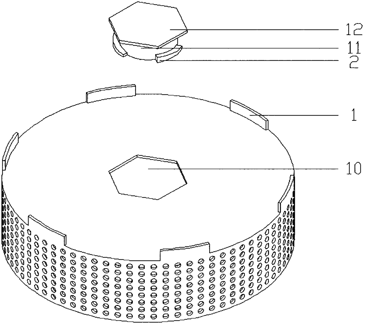
[0216] This embodiment is a driven centrifugal unit with a hexagonal lock hole (10), and its structural schematic diagram is shown in figure 2 .
[0217] Such as figure 2 shown, according to Figure 8 The method (8) in turn passes through the following steps:
[0218] The first step: select the steel plate;
[0219] The second step: stamping and forming the body part B embryo body (that is, having part of the rear end cap and the first metal part of the centrifuge bowl);
[0220] Step 3: Injection molding the main body B of the centrifugal cover precursor;
[0221] Step 4: Process the centrifugal cover precursor through the closing process of the closing machine to form the centrifugal cover and then form it into a driven centrifugal unit;
[0222] The driven centrifugal unit obtained in 4 steps in total has: centrifugal cover, feeding hole, centrifugal drum (7) and the centrifugal through hole (6) on it, locking structure-card located at the junction between the edge ...
Embodiment 3
[0224] This embodiment is a driven centrifugal unit with an independent rear end cover (17), and its structural schematic diagram is shown in Fig. 3 (including Figure 3A and Figure 3B).
[0225] As shown in Figure 3, according to Figure 7 The method (1) in turn passes through the following steps:
[0226] The first step: select the steel plate;
[0227] The second step: punching the centrifugal through hole;
[0228] The third part: rolling and connecting into a centrifugal drum (that is, the first metal part with a centrifugal drum);
[0229] Step 4: Injection molding the main body A;
[0230]The main part A obtained in 4 steps in total has: the centrifugal cover (8), the feeding hole (9), the centrifugal drum (7) and the centrifugal through hole on it, and the rear end cover locking structure located outside the bottom end of the main part A- The arc-shaped protrusion (2A), the first sealing surface (19) located on the outer edge of the centrifugal cover, and the seco...
PUM
 Abstract
Description
Claims
Application Information
 - R&D
- Intellectual Property
- Life Sciences
- Materials
- Tech Scout
- Unparalleled Data Quality
- Higher Quality Content
- 60% Fewer Hallucinations
Browse by: Latest US Patents, China's latest patents, Technical Efficacy Thesaurus, Application Domain, Technology Topic, Popular Technical Reports.
© 2025 PatSnap. All rights reserved.Legal|Privacy policy|Modern Slavery Act Transparency Statement|Sitemap|About US| Contact US: help@patsnap.com


