
Tooth implantation structure

A dental implant and dental implant technology, applied in dental implant, dentistry, dental prosthetics, etc., can solve problems such as poor mechanical properties and biocompatibility, unreasonable implant structure design, poor axial rotation resistance, etc. Achieve the effect of increasing biocompatibility, improving implant comfort and prolonging service life

Inactive Publication Date: 2018-08-28
THE FIRST AFFILIATED HOSPITAL OF JINZHOU MEDICAL UNIV
View PDF5 Cites 2 Cited by
  • Summary
  • Abstract
  • Description
  • Claims
  • Application Information

AI Technical Summary

Problems solved by technology

[0003] Among them, the structural design of the dental implant is unreasonable, and its mechanical properties and biocompatibility are poor. The stability of the implant is poor; after implantation, it is not possible to add other substances such as biological factors to increase the stability of the implant in the weak bone such as the bottom; and the gap between the implant and the retention abutment is mostly ordinary Threaded connection, the connection is not tight enough, and it is easy to cause impurities to enter the connection thread gap, which will affect the fixed connection between the two
In addition, the fixed abutment and the denture are often connected by direct plug-in, which has poor resistance to axial rotation, and there are problems that the connection is not stable enough, easy to loosen and fall off

Method used


Image

  • Tooth implantation structure
  • Tooth implantation structure
  • Tooth implantation structure

Examples


Embodiment Construction

[0018] A specific embodiment of the present invention will be described in detail below in conjunction with the accompanying drawings, but it should be understood that the protection scope of the present invention is not limited by the specific embodiment.

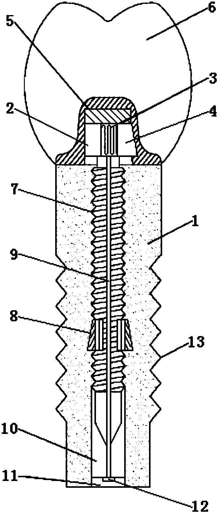
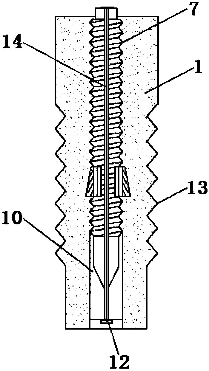
[0019] like Figure 1-3 As shown, the embodiment of the present invention provides a dental implant structure, including an implant 1, a fixed base 2 and a denture 6, the side of the fixed base 2 is provided with a first groove 2-1, and the first A spring 3 is arranged in the groove 2-1, and the other end of the spring 3 is connected with a slider 4; a buffer pad 5 is arranged on the fixed base 2, and a second groove is opened on the buffer pad 5, The size of the second groove matches the slider 4; the buffer pad 5 is provided with a denture 6; the fixed base 2 is threadedly connected with a threaded rod 7, and the threaded rod 7 is connected to the implanted The threaded holes provided in the body 1 match; the threaded r...


PUM


Abstract

The invention discloses a tooth implantation structure. The tooth implantation structure comprises an implantation body, a fixing drill base and false teeth, wherein the fixing drill base is providedwith a crash pad, the crash pad is provided with the false teeth; the lower portion of the fixing base is in threaded connection with a threaded rod, the threaded rod is matched with a threaded hole formed in the implantation body; the whole structure is simple, the implantation body and the fixing drill base are connected integrally by bonding or welding, the connecting methods of the implantation body and fixing drill base are simple, the connection is firm and reliable, the whole force receptivity is good, and the production is convenient; one end of a connecting rod is fixed on the fixingdrill base, and the other end of the connecting rod is fixed at a closed end of the bottom face of the implantation body, so that the close contact between the structure and the implantation body is achieved, and the fixing and stable effects are achieved; the crash pad is arranged between the false teeth and the fixing drilling base, and the distribution of the upper jaw force of the dentition can be adjustable, so that the periodontal traumatism is avoided, the load of artificial implant tooth can be reduced, and the service life of the artificial implant tooth is prolonged; holes are further formed in the false teeth and the fixing drill base, so that the false teeth and the fixing base can be in embedded connection to prevent the artificial implant tooth from falling off.

Description

technical field [0001] The invention relates to the technical field of oral artificial dental implants, in particular to a dental implant structure. Background technique [0002] Most of the dental implant structures used in oral dental implant surgery currently include implants, retaining abutments and dentures. After the implant body is pre-embedded in the gum, a retention abutment is installed above it, and the retention abutment is exposed on the surface of the gum and the denture is installed to realize the implantation of the denture. [0003] Among them, the structural design of the dental implant is unreasonable, its mechanical properties and biocompatibility are poor, and it will be repelled with human tissue after long-term use, which will affect its service life; When implanted, the stability is poor; after implantation, it is not possible to add other substances such as biological factors to increase the stability of the implant at the weak bone such as the bott...

Claims


Application Information

Patent Timeline
Patent Type & Authority Applications(China)
IPC IPC(8): A61C8/00
CPCA61C8/0037A61C8/005A61C8/0086
Inventor 崔玲玲王晶
Owner THE FIRST AFFILIATED HOSPITAL OF JINZHOU MEDICAL UNIV
Learn More