
Posterior cruciate ligament tibia positioner

A cruciate ligament and locator technology, applied in the field of medical devices, can solve problems such as damage to blood supply, soft tissue obstruction, unclear vision, etc., and achieve the effects of reducing soft tissue obstruction, enhancing possibility, and being flexible and light in operation.

Pending Publication Date: 2018-08-28
谷守滨
View PDF0 Cites 0 Cited by
  • Summary
  • Abstract
  • Description
  • Claims
  • Application Information

AI Technical Summary

Problems solved by technology

The posterior cruciate ligament tibial locator is an essential surgical instrument in the operation of patients with posterior cruciate ligament repair of the knee joint. Existing patients with posterior cruciate ligament repair of the knee joint usually use an anterior approach for positioning. Unclear, blood supply and other risks, this situation requires the operator to have a wealth of clinical practice experience

Method used


Image

  • Posterior cruciate ligament tibia positioner
  • Posterior cruciate ligament tibia positioner
  • Posterior cruciate ligament tibia positioner

Examples


Embodiment 1

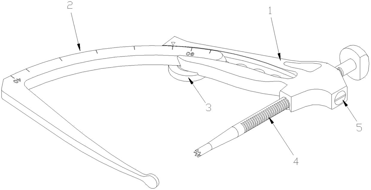
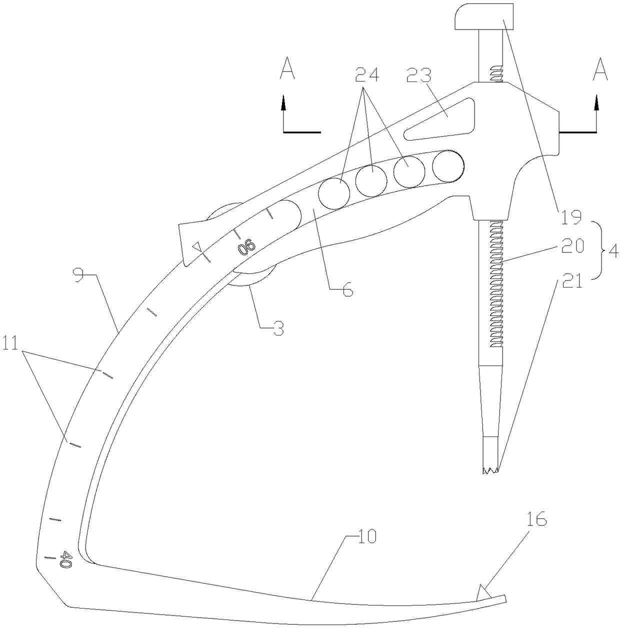
[0029] Embodiment 1 of the present invention: a posterior cruciate ligament tibial positioner, such as figure 1 , figure 2 , image 3 , Figure 4 with Image 6 As shown, it includes a guide handle 1, a positioning hook 2, a locking wheel 3, a sleeve 4 and a locking mechanism 5, the guide handle 1 is provided with a chute 6, and the positioning hook 2 is slidably connected in the chute 6, The sliding of the positioning hook 2 in the chute 6 can realize the relative approach and distance between the guide handle 1 and the positioning hook 2, so as to adjust and position the distance of the posterior cruciate ligament tibia of different patients. Threaded hole 7, the locking wheel 3 is bolt-shaped, and the locking wheel 3 is threaded in the threaded hole 7, and the locking wheel 3 can compress and fix the positioning hook 2 and the guide handle 1 by screwing together. The guide handle 1 is penetrated with a through hole 8, and the through hole 8 is provided with a sleeve 4....

Embodiment 2

[0033] Embodiment 2: A kind of posterior cruciate ligament tibial positioner, such as figure 1 , Figure 5 with Image 6 As shown, it includes a guide handle 1, a positioning hook 2, a locking wheel 3, a sleeve 4 and a locking mechanism 5, the guide handle 1 is provided with a chute 6, and the positioning hook 2 is slidably connected in the chute 6, The sliding of the positioning hook 2 in the chute 6 can realize the relative approach and distance between the guide handle 1 and the positioning hook 2, so as to adjust and position the distance of the posterior cruciate ligament tibia of different patients. Threaded hole 7, the locking wheel 3 is bolt-shaped, and the locking wheel 3 is threaded in the threaded hole 7, and the locking wheel 3 can compress and fix the positioning hook 2 and the guide handle 1 by screwing together. The guide handle 1 is penetrated with a through hole 8, and the through hole 8 is provided with a sleeve 4. The sleeve 4 is a tubular structure, and ...


PUM


Abstract

The invention relates to the field of medical apparatuses and instruments, in particular to a posterior cruciate ligament tibia positioner. The posterior cruciate ligament tibia positioner comprises aguiding handle, a positioning hook, a locking wheel, a sleeve and a locking mechanism; a sliding groove is formed in the guiding handle, the positioning hook is in sliding connection with the interior of the sliding groove, a threaded hole is formed in the sliding groove, a locking wheel is in threaded connection with the threaded hole, a through hole is formed in the guiding handle, a sleeve isin sliding connection with the through hole, and the sleeve and the guiding handle are fixed through the locking mechanism. The posterior cruciate ligament tibia positioner is easy and convenient to operate, by adopting the posterior medial approach placement mode, positioning and repairing operation are performed, soft tissue obstruction inside a knee joint cavity, sight blur and other problems and blood supply damage risk in the operation process are reduced, the ligament residual end does not need to be cut off, ligament healing and blood vessel neuralization are facilitated, and the operation success probability is increased.

Description

technical field [0001] The invention relates to the field of medical instruments, in particular to a posterior cruciate ligament tibial positioner. Background technique [0002] In daily life, ordinary people are prone to ligament strains during strenuous activities, and when making rapid movements beyond the range of joint motion, the posterior cruciate ligament is easily torn or completely ruptured due to passive stretching, often accompanied by sprains And fractures, ligament injuries should be promptly diagnosed and treated and reconnected. The posterior cruciate ligament tibial locator is an essential surgical instrument in the operation of patients with posterior cruciate ligament repair of the knee joint. Existing patients with posterior cruciate ligament repair of the knee joint usually use an anterior approach for positioning. Risks such as unclear and disrupted blood supply require the operator to have rich clinical practice experience. In order to reduce the ris...

Claims


Application Information

Patent Timeline
IPC IPC(8): A61B90/11A61B90/14A61B90/17
CPCA61B90/11A61B90/14A61B90/17
Inventor 谷守滨
Owner 谷守滨
Learn More