mmWave multi-cell interference suppression method for minimizing base station transmitting power

A transmission power and interference suppression technology, applied in space transmit diversity, diversity/multi-antenna systems, transmission systems, etc., can solve problems such as overestimation of performance evaluation, limited energy supply, increased interference, etc., to overcome limitations and overhead Reduced, performance-evaluated accurate effects

Active Publication Date: 2018-08-24
CHONGQING UNIV OF POSTS & TELECOMM
View PDF5 Cites 6 Cited by
  • Summary
  • Abstract
  • Description
  • Claims
  • Application Information

AI Technical Summary

Problems solved by technology

However, the effect of ground reflection (first-order reflection) is rarely included in most of the literature because it is widely and deeply considered that ground reflection is not a dominant factor that significantly affects performance evaluation
This traditional channel model for mmWave radios (based only on LOS paths) can lead to significant overestimation (or underestimation) in performance estimates due to omission of non-negligible constructive (or destructive) effects of reflections
[0003] Currently, in the mmWave multi-cell scenario, the number of mmWave base stations is far greater than the number of macro base stations, but the problem of minimizing the transmit power of base stations is not considered, so the interference increases with the increase of the number of base stations
Moreover, not only because of the rapid increase in traffic volume due to the popularity of smartphones, but also because of the limited supply of energy due to rising energy prices

Method used


Image

  • mmWave multi-cell interference suppression method for minimizing base station transmitting power
  • mmWave multi-cell interference suppression method for minimizing base station transmitting power
  • mmWave multi-cell interference suppression method for minimizing base station transmitting power

Examples


Embodiment Construction

[0031] The technical solutions in the embodiments of the present invention will be described clearly and in detail below with reference to the drawings in the embodiments of the present invention. The described embodiments are only some of the embodiments of the invention.

[0032] The technical scheme that the present invention solves the problems of the technologies described above is:

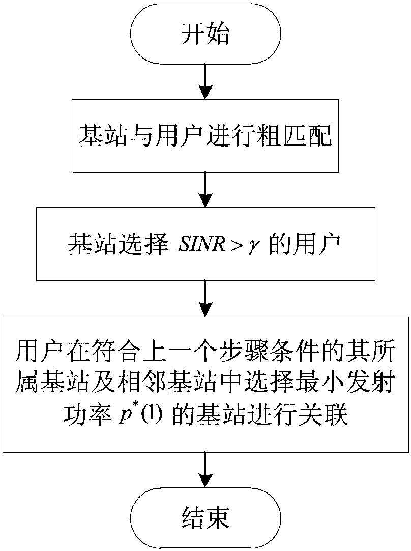
[0033] figure 1 The flow chart of the mmWave multi-cell interference suppression method for minimizing base station transmit power for joint user association and beamwidth selection is described in detail as follows.

[0034] figure 2 is the system model diagram, h t is the height of mmWave base station, h r user height, ξ m is the main lobe beam width, θ represents the reflection angle relative to the ground plane, R is the distance between the base station and the user, and d is the horizontal distance between the base station and the user.

[0035] Step 1: Jointly process the Gauss...


PUM


Abstract

The invention relates to the technical field of mmWave multi-cell interference suppression, and discloses a mmWave multi-cell interference suppression method for minimizing base station transmitting power in combination with user association and beam width selection. The method comprises the following steps: combining a Gaussian antenna model with an mmWave dual-ray channel model as a system model, under the system model, converting the problem of minimizing the base station transmitting power into two methods of user association and optimal beam width selection, firstly, selecting a user withSINR greater than a threshold after pairing of base stations and users under a distributed framework, selecting, by the user, the base station with the smallest transmitting power among the neighboring base stations for association, and then selecting the optimal beam width by using a particle swarm optimization method. The invention designs a user association and beam width selection method, which reduces the computational complexity and reduces the inter-cell interference while ensuring that the base station transmission power is minimized.

Description

technical field [0001] The invention belongs to the field of mobile communication, and in particular relates to the technical field of mmWave multi-cell interference suppression. Background technique [0002] In recent years, millimeter wave (mmWave) communications will play a key role in improving the throughput, reliability and security of next-generation wireless networks. These improvements are achieved through the large bandwidth available in this frequency band and the use of highly directional links that will be used to overcome the large path loss at mmWave frequencies. For high analytical tractability, the sector model is a popular choice when modeling the radiation pattern of a directional antenna. However, in the sector model, only two constant gains are used to characterize the mainlobe and sidelobes, respectively, without any transition between them. An obvious disadvantage of this approach to the idealized situation is that in practical applications the criti...

Claims


Application Information

Patent Timeline
Patent Type & Authority Applications(China)
IPC IPC(8): H04B7/06H04B7/08
CPCH04B7/0626H04B7/0695H04B7/088Y02D30/70
Inventor 张祖凡余鸿晖
Owner CHONGQING UNIV OF POSTS & TELECOMM
Why Eureka
Try Eureka