Eureka AIR delivers breakthrough ideas for toughest innovation challenges, trusted by R&D personnel around the world.

Self-driven dual-track radar flow measurement system

A dual-track, self-driven technology, applied to radio wave measurement systems, measurement devices, engine components, etc., can solve the problems of increased measurement and maintenance costs, inability to measure water flow velocity in time, and reduced accuracy of measurement results. The accuracy of the results is guaranteed, the cost of measurement and maintenance is low, and the cost of operation and maintenance is reduced.

Pending Publication Date: 2018-08-24
北京艾力泰尔信息技术股份有限公司
View PDF0 Cites 8 Cited by
  • Summary
  • Abstract
  • Description
  • Claims
  • Application Information

AI Technical Summary

Problems solved by technology

The shipborne ADCP measurement system has the advantages of fast flow measurement and convenient operation. However, when there are many floating objects in the river, the water quality is turbid, or the water flow rate is too fast, the accuracy of the measurement results obtained will be greatly reduced, and even cannot be normal. work, and when it encounters floods, it cannot measure the water flow velocity in time
The fixed flow measurement system generally installs multiple flow meters on the bridge, and obtains the flow measurement results by comprehensively processing and analyzing the data obtained by each flow meter. However, multiple flow meters need to be installed on a river section. This will inevitably greatly increase the cost of measurement and maintenance, making it difficult to popularize

Method used


Image

  • Self-driven dual-track radar flow measurement system
  • Self-driven dual-track radar flow measurement system
  • Self-driven dual-track radar flow measurement system

Examples


Embodiment Construction

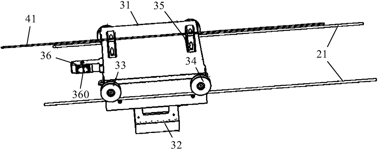
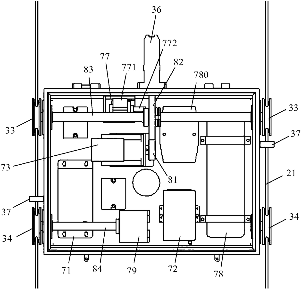
[0021] Such as Figure 1 to Figure 10 As shown, the self-driven dual-track radar flow measurement system of the present invention includes columns 10 on both sides of the river, and two cables 21 forming a horizontal (or substantially horizontal) cableway are pulled between the two columns 10, and the cableway is located at Above the water surface of the river, as shown in the figure, a flow measuring vehicle 30 is installed on the rope 21, and a station telemetry center 60 is arranged on one side of the river, wherein: the flow measuring vehicle 30 includes a rectangular shell 31, and the bottom surface of the shell 31 is equipped with a radar wave Flow measuring instrument 32, both sides of housing 31 are equipped with driving pulley 33, driven pulley 34 and protective ring 37, and flow measuring vehicle 30 can be realized on the cableway by the rotation of driving pulley 33 and driven pulley 34 on the rope 21. Forward and backward movement, the rope 21 runs through the prot...


PUM


Abstract

The present invention discloses a self-driven dual-track radar flow measurement system with unattended operation and capable of real-time and automatic monitoring of hydrological parameters such as ariver channel flow rate and a water level. The system comprises stand columns arranged at two sides of a river channel, two ropes are pulled and connected between the two stand columns, a flow measurement vehicle is arranged on the ropes, and one side of the river channel is provided with a station building remote sensing center. The flow measurement vehicle comprises a housing, the bottom surfaceof the housing is provided with a radar wave flow measurement instrument, two sides of the housing are provided with driving and driven pulleys and guard rings, the ropes penetrate the guard rings, the housing is internally provided with a controller, a stepping motor, a traveling drive mechanism and a short-distance wireless communication device, the controller is connected with a radar wave flow measurement instrument, the stepping motor and the short-distance wireless communication device, and the stepping motor controls rotation of the driving pulleys through the travelling drive mechanism. The station building remote sensing center comprises a solar panel, the solar panel is connected with the remote sensing terminal control box through a storage battery, and the remote sensing terminal control box is in wireless communication with the flow measurement vehicle.

Description

technical field [0001] The invention relates to a self-driven dual-track radar current measurement system, which belongs to the technical field of radar wave current measurement. Background technique [0002] River flow measurement is an important part of hydrological work, and various data obtained by it play an important role in the full utilization of water resources and the development of flood control and flood fighting work. The currently used flow measurement technologies mainly include ship-borne ADCP measurement system and fixed flow measurement system. The shipborne ADCP measurement system has the advantages of fast flow measurement and convenient operation. However, when there are many floating objects in the river, the water quality is turbid, or the water flow rate is too fast, the accuracy of the measurement results obtained will be greatly reduced, and even cannot be normal. work, and when encountering floods, it cannot measure the flow velocity of the water ...

Claims


Application Information

Patent Timeline
Patent Type & Authority Applications(China)
IPC IPC(8): G01S13/58G01P5/00G01F23/284
CPCG01F23/284G01P5/00G01S13/58
Inventor 李祖华黄国新尹宪文李玉奎王超
Owner 北京艾力泰尔信息技术股份有限公司
Why Eureka
Eureka Blog
Learn More