Arch bridge boom structure

A suspension rod and arch bridge technology, which is applied in the field of suspension rod arch bridge structure system, can solve the problems of overstrength, deterioration of the bearing capacity of adjacent suspension rods, loss of technical advantages of suspension rod arch bridges, etc., to achieve improved safety, small screw size, Eliminate the effect of detecting blind spots

Pending Publication Date: 2018-08-24
SHENZHEN MUNICIPAL DESIGN & RES INST
View PDF0 Cites 1 Cited by
  • Summary
  • Abstract
  • Description
  • Claims
  • Application Information

AI Technical Summary

Problems solved by technology

[0003] The new specification puts forward new requirements for the longitudinal girders of CFST arch bridges. Although the safety of CFST arch bridges has been improved, it does not consider that the adjacent suspenders work in the same environment. When one suspender breaks, the adjacent suspenders The load-bearing capacity of the rods is likely to have deteriorated, and when a single suspender breaks, it will generate a certain impact force, so the cable force transmitted to the adjacent suspender is usually greater than 1.5 times the original cable force, which greatly increases the strength of the adjacent suspender. Therefore, the main longitudinal girder of the continuous structural system should meet the bearing capacity requirement of 2 times the span of the sling and cannot fundamentally solve the risk of bridge collapse
The design of the longitudinal girder is too strong, and the technical advantages of the hanger arch bridge are lost

Method used


Image

  • Arch bridge boom structure
  • Arch bridge boom structure
  • Arch bridge boom structure

Examples


Embodiment Construction

[0029] The following will clearly and completely describe the technical solutions in the embodiments of the present invention with reference to the accompanying drawings in the embodiments of the present invention. Obviously, the described embodiments are only some, not all, embodiments of the present invention. Based on the embodiments of the present invention, all other embodiments obtained by persons of ordinary skill in the art without making creative efforts belong to the protection scope of the present invention.

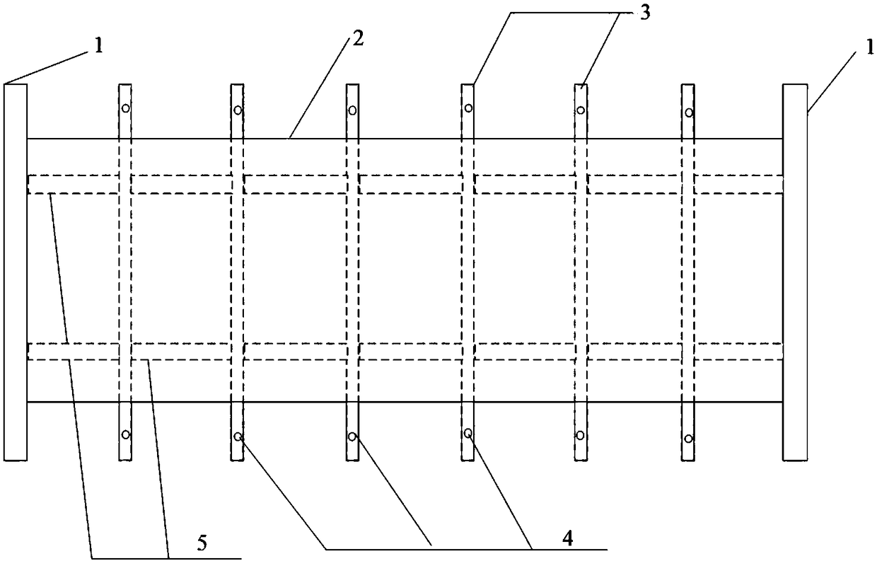
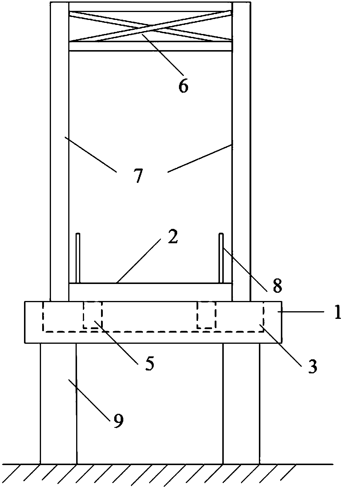
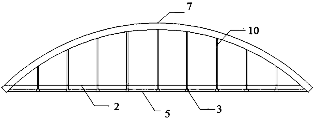
[0030] The object of the present invention is to provide a suspension rod structure for an arch bridge to solve the above-mentioned problems in the prior art. The structural system facilitates the removal and replacement of the suspension rod due to the overhang of the beam. At the same time, the new suspension rod structure can be installed on the bridge deck The bridge is directly connected to the arch ribs and beams, and stretched on the bridge deck, which c...


PUM


Abstract

The invention discloses an arch bridge boom structure which comprises bridge piers, horizontal beams, longitudinal beams, a bridge floor and arch ribs which are sequentially arranged from bottom to top, wherein the horizontal beams and the longitudinal beams are mutually in lap joint and fixed to the bridge piers, the bridge floor is arranged at the tops of the horizontal beams, the arch ribs arearranged on the two sides of the bridge floor, the top ends of the arch ribs on the two sides of the bridge floor are fixedly connected through steel supports, booms are evenly distributed among the arch ribs and the bridge floor, the length of the horizontal beams is larger than the width of the bridge floor, the bottom ends of the booms are in threaded connection to the two ends of the horizontal beams, and the top ends of the booms are fixed to the arch ribs. The invention aims at providing the arch bridge boom structure. According to the structure system, as the horizontal beams extends outwards, the booms can be disassembled and replaced conveniently; meanwhile, the novel boom structure can be directly connected with the arch ribs and the horizontal beams on the bridge floor and can be stretched and drawn on the bridge floor, so that the problems of rust and corrosion of existing boom anchoring areas is completely solved, and safety of a boom arch bridge is improved.

Description

technical field [0001] The invention relates to the technical field of suspension rod arch bridge bridge structure system, in particular to an arch bridge suspension rod structure. Background technique [0002] Many bridge collapses caused by broken cables at home and abroad in recent years are mainly caused by corrosion and broken suspenders, which can be greatly improved by setting small longitudinal girders in the longitudinal direction of the bridge. According to the "Code for Design of Highway Concrete-filled Steel Tube Arch Bridge JTG-T D65-06-2015" promulgated in 2015, the bridge deck girders (slabs) of mid- and bottom-through concrete-filled steel tube arch bridges must adopt a continuous structural system, and the main The longitudinal girder shall meet the bearing capacity requirement of 2 times the span of the sling. [0003] The new specification puts forward new requirements for the longitudinal girders of CFST arch bridges. Although the safety of CFST arch bri...

Claims


Application Information

Patent Timeline
IPC IPC(8): E01D4/00E01D19/00
CPCE01D4/00E01D19/00
Inventor 姜瑞娟陈宜言于芳易小纬
Owner SHENZHEN MUNICIPAL DESIGN & RES INST
Why Eureka
Try Eureka