
Parking lot electric vehicle automatic charging system

An electric vehicle, automatic charging technology, applied in electric vehicle charging technology, electric vehicles, buildings where cars are parked, etc., can solve the problems of heavy workload, poor safety, poor reliability, and insufficient cable length, and reduce workload. , to avoid the effect of entanglement

Active Publication Date: 2018-08-24
重庆复融科技有限公司
View PDF4 Cites 6 Cited by
  • Summary
  • Abstract
  • Description
  • Claims
  • Application Information

AI Technical Summary

Problems solved by technology

[0002] Under the pressure of decreasing oil resources around the world and energy conservation and emission reduction in various regions, new energy vehicles, mainly pure electric vehicles and plug-in hybrid vehicles, are the future direction of development. However, land resources in cities are very tight, so Many places will centrally manage the vehicles parked by users everywhere. In other words, all parked vehicles will be transported to a place for unified management through a transfer device, such as the establishment of a three-dimensional parking lot. In the process of managing these vehicles , the car owner will leave after parking the car. For electric vehicles, they need to be charged. If it is too far away, the cable may not be long enough, or the cable may be scratched or entangled with the internal structure of the parking lot, causing problems such as poor safety and reliability; Charging is carried out after transportation, but the owner has already left after parking. At this time, if the staff manually connect the electric vehicle to the charging device, due to the large number of parked vehicles, the workload of the staff will be heavy, and it is not convenient for charging management.

Method used


Image

  • Parking lot electric vehicle automatic charging system
  • Parking lot electric vehicle automatic charging system
  • Parking lot electric vehicle automatic charging system

Examples


Embodiment Construction

[0027] The following is further described in detail through specific implementation methods:

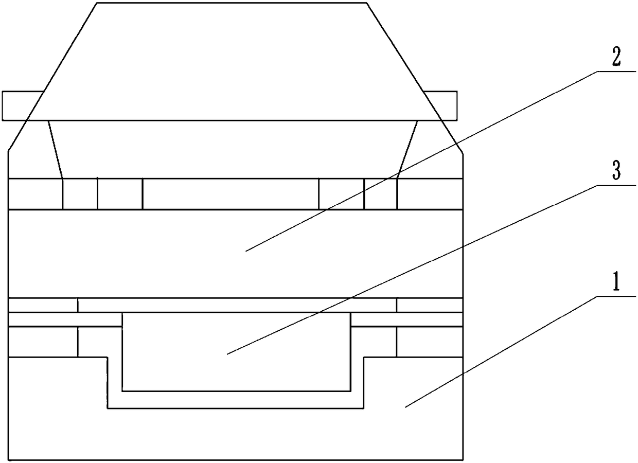
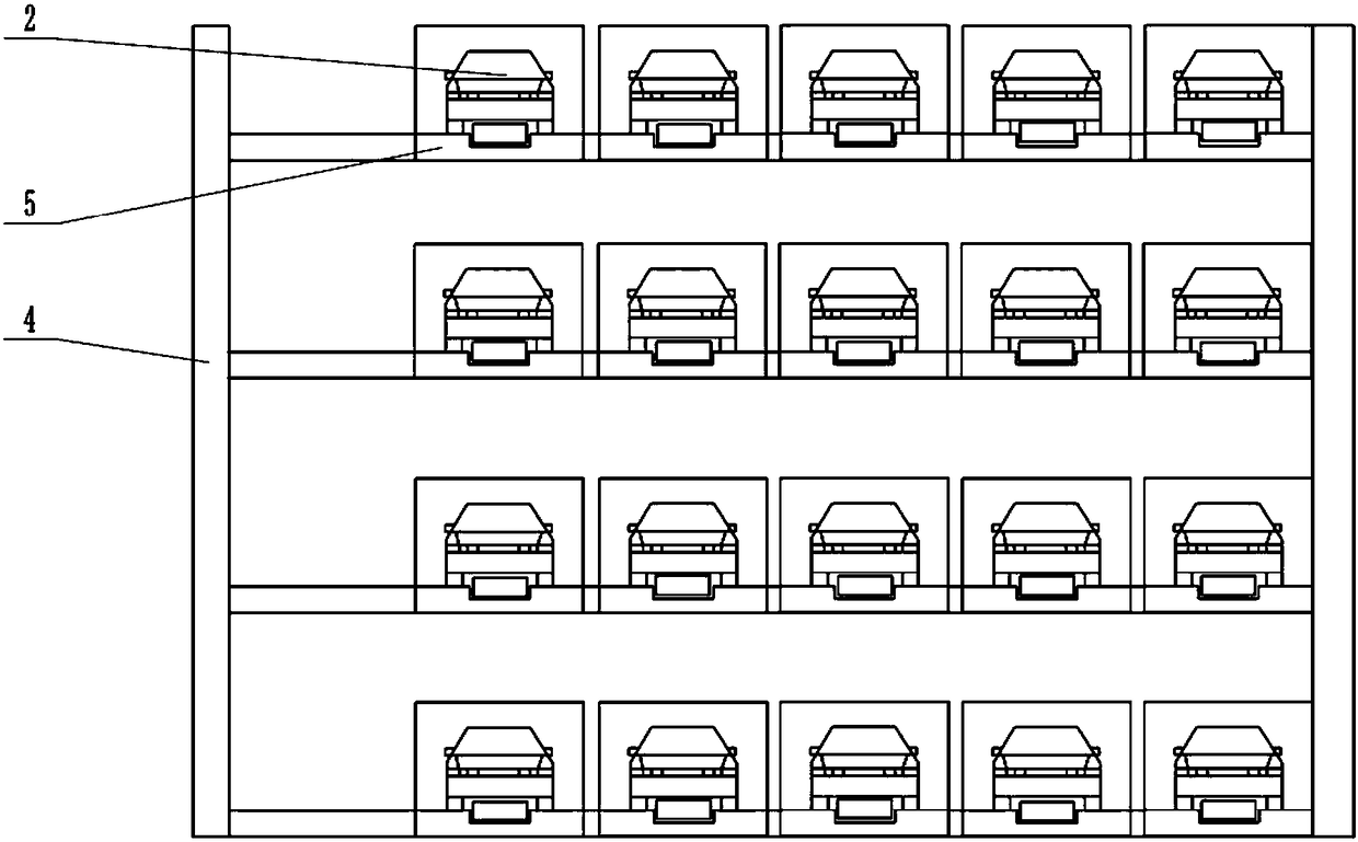
[0028] The reference signs in the drawings of the description include: ground parking space 1, electric vehicle 2, trolley 3, three-dimensional parking bracket 4, vehicle loading plate 5, female head 6, and charging head 7.

[0029] Such as Figure 5 As shown, the charging management system includes a server, a user terminal, a management terminal and a control terminal. The server is respectively connected to the user terminal, the management terminal and the control terminal through a wireless communication module. The wireless communication module can be selected Bluetooth communication module, WIFI communication module or Zigbee module;

[0030] 1. The user terminal includes:

[0031] Parking reservation module, the parking reservation module is used for the user to send parking request information to the ground parking vacancy query module in the server when the user needs to ...


PUM


Abstract

The invention relates to the field of parking lot electric vehicle charging and in particular discloses a parking lot electric vehicle automatic charging system. The parking lot electric vehicle automatic charging system comprises an original parking space, where a vehicle owner parks an electric vehicle, a target parking space, where the electric vehicle is conveyed, a connecting device and an adapter device, wherein the connecting device is connected with an electric vehicle charging device on the target parking space, and the adapter device is conveyed together with the electric vehicle when a transferring device automatically conveys the electric vehicle; an electric vehicle charging plug is arranged on the adapter device; and the adapter device can be in automatic communication with the connecting device when being conveyed to the target parking space by the transferring device. Compared with the prior art, the parking lot electric vehicle automatic charging system has the advantage that a purpose of automatically charging the parked electric vehicle needing to be charged after the parked electric vehicle needing to be charged is automatically conveyed to another parking spaceis realized.

Description

technical field [0001] The invention relates to the field of electric vehicle charging in a parking lot, and specifically discloses an automatic charging system for an electric vehicle in a parking lot. Background technique [0002] Under the pressure of decreasing oil resources around the world and energy conservation and emission reduction in various regions, new energy vehicles, mainly pure electric vehicles and plug-in hybrid vehicles, are the future direction of development. However, land resources in cities are very tight, so Many places will centrally manage the vehicles parked by users everywhere. In other words, all parked vehicles will be transported to a place for unified management through a transfer device, such as the establishment of a three-dimensional parking lot. In the process of managing these vehicles , the car owner will leave after parking the car. For electric vehicles, they need to be charged. If it is too far away, the cable may not be long enough,...

Claims


Application Information

Patent Timeline
IPC IPC(8): B60L11/18E04H6/08E04H6/18
CPCB60L53/00E04H6/08E04H6/18Y02T10/70Y02T10/7072Y02T90/12Y02T90/14
Inventor 丁跃华崔志丹周余张伟王鹏
Owner 重庆复融科技有限公司
Learn More