Optical film manufacturing method

A manufacturing method and technology for optical films, which are applied in chemical instruments and methods, bonding methods for surface pretreatment, optical components, etc., and can solve problems such as appearance defects and residual foreign matter.

Active Publication Date: 2018-08-21
NITTO DENKO CORP
View PDF12 Cites 5 Cited by
  • Summary
  • Abstract
  • Description
  • Claims
  • Application Information

AI Technical Summary

Problems solved by technology

However, in the conventional production method, when the surface of the polarizing plate, transparent protective film, etc., before coating the adhesive composition, etc., foreign matter such as debris or dust adheres, or when the adhesive composition contains minute foreign matter, the Foreign matter remains in the layer, and as a result, appearance defects may occur

Method used


Image

  • Optical film manufacturing method
  • Optical film manufacturing method
  • Optical film manufacturing method

Examples


Embodiment 1

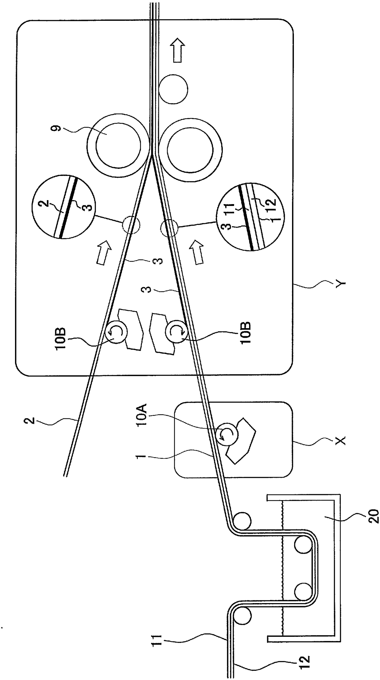
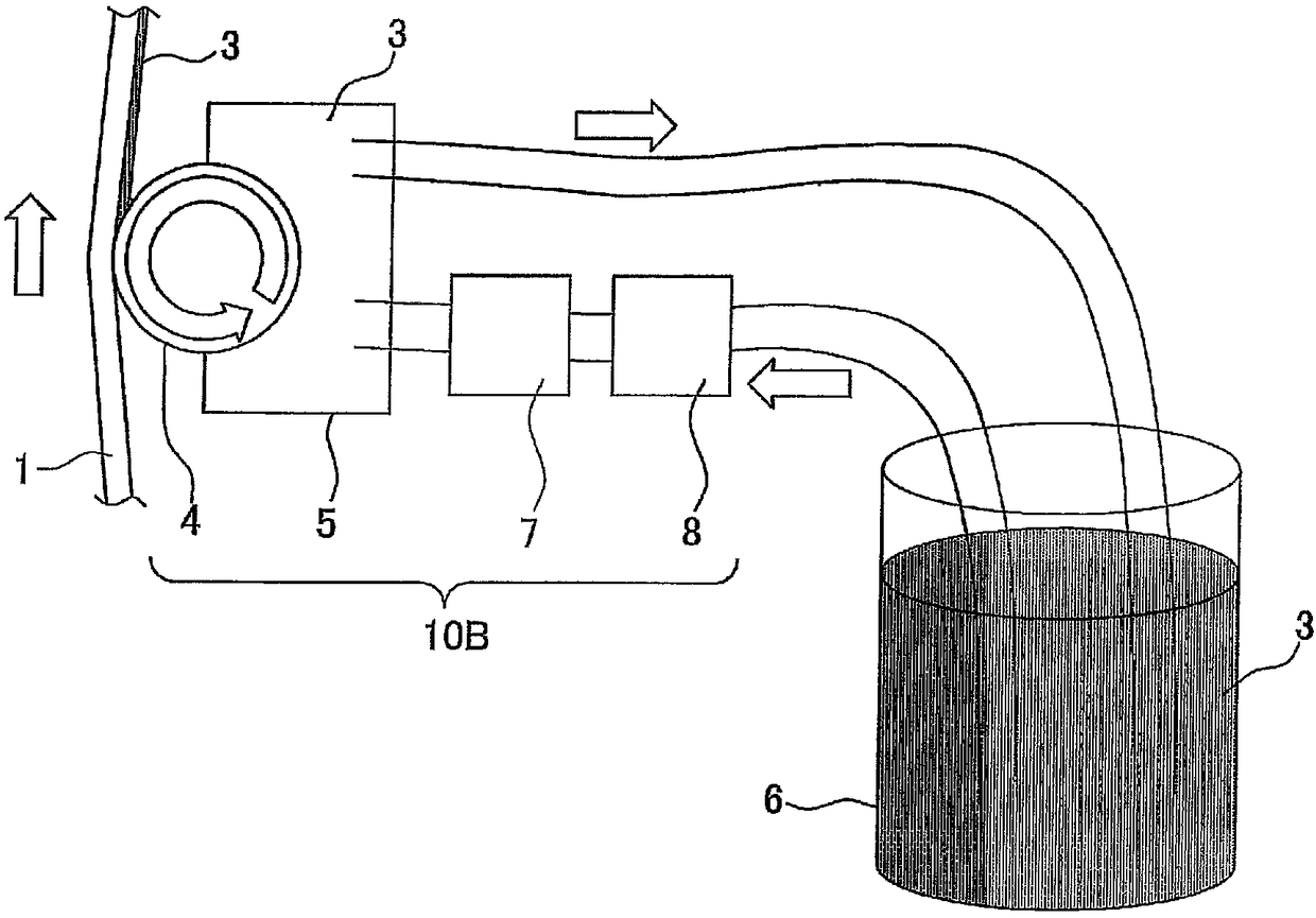
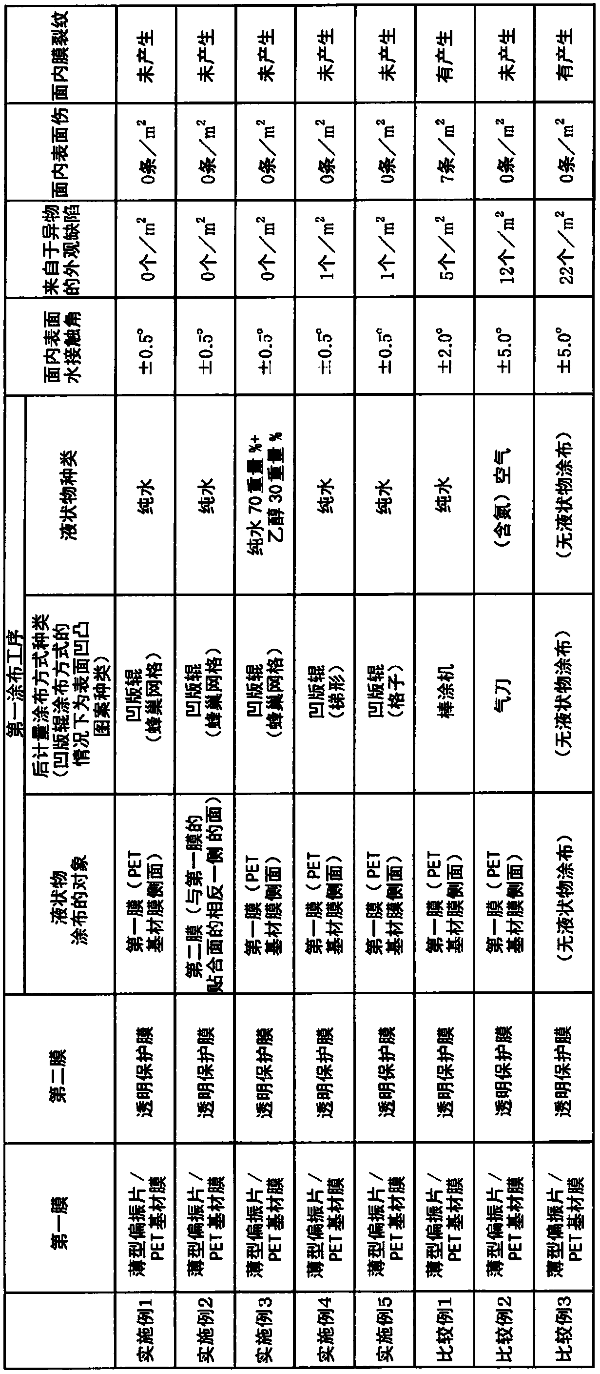
[0122] exist figure 1 , 2 In the production line shown, a gravure roll coating system 10A equipped with a gravure roll 4 (both are MCD coaters (manufactured by Fuji Machinery Co., Ltd.)) (groove shape: honeycomb grid pattern, number of groove lines of the gravure roll: 1000 bar / inch, rotation speed ratio 140%), to the side of the PET base film 12 of the first film 1 which is a laminate of the polarizing plate 11 and the PET base film 12, the liquid is applied to remove the Foreign matter and air bubbles on the side of the film 12. Then, using the gravure roll coating method 10B, the adhesive composition 3 is applied to the side of the polarizer 11 of the first film and the bonding surface of the second film, thereby removing foreign matter and air bubbles. A polarizing film was produced while air bubbles were formed. It should be noted that the adhesive composition 3 was coated on the first film and the second film so that the thickness of the adhesive layer after drying was ...

Embodiment 2~5、 comparative example 1~3

[0126] An optical film was produced in the same manner as in Example 1, except that the type of film to be subjected to the first coating step, the type of coating method, and the viscosity and composition of the liquid were changed to those described in Table 1. Commercially available coating devices were used in the bar coater coating system and the air knife coating system, respectively.

[0127]

[0128] The number of appearance defects in the adhesive layer of the polarizing film (the number of appearance defects due to foreign matter and from (bonded) air bubbles (number / m 2 )). The results are shown in Table 1.

[0129]

[0130] The in-plane surface water contact angle was measured at 10 points equally spaced in the film width direction (total width: 1500 mm) using DM-701 manufactured by Kyowa Interface Science Co., Ltd. The smaller the number of appearance defects present on the measurement surface, the smaller the variation in the water contact angle. The results...


PUM

PropertyMeasurementUnit
thicknessaaaaaaaaaa
heightaaaaaaaaaa
thicknessaaaaaaaaaa

Abstract

The purpose of the present invention is to provide an optical film manufacturing method with which generation of appearance defects caused by foreign substances and/or bubbles can be prevented even ifthe optical film is thin. Provided is a method for manufacturing an optical film that includes a laminate structure in which at least a first film and a second film are bonded to each other through an adhesive layer and/or a pressure-sensitive adhesive layer comprising a cured product layer of adhesive composition or a pressure-sensitive adhesive composition, said optical film manufacturing method including a first coating process for removing foreign substances by coating at least either the surface of the first film opposite the surface to be bonded to the second film or the surface of thesecond film opposite the surface to be bonded to the first film with a liquid material having a viscosity of 1 to 10000 cP using a gravure roll before bonding the first film and the second film.

Description

technical field [0001] The present invention relates to an optical device comprising a laminated structure in which at least a first film and a second film are laminated via an adhesive layer or an adhesive layer composed of an adhesive composition or a cured product layer of the adhesive composition. Membrane manufacturing method. Background technique [0002] Liquid crystal display devices are rapidly expanding the market for watches, mobile phones, PDAs, notebook personal computers, monitors for personal computers, DVD players, TVs, and the like. A liquid crystal display device is a device that visualizes a polarization state by switching liquid crystals, and uses a polarizing plate based on the display principle. Especially in applications such as TV, high brightness, high contrast, and wide viewing angle are gradually required, and high transmittance, high polarization degree, high color reproducibility, etc. are gradually required in polarizing films. [0003] As a p...

Claims


Application Information

Patent Timeline
Patent Type & Authority Applications(China)
IPC IPC(8): G02B5/30B05D1/28B05D7/04B32B27/00B32B37/12C09J5/00C09J201/00
CPCB05D7/04B05D1/28B32B27/00B32B37/12C09J5/00C09J201/00G02B5/30B29D11/00644B29D11/0073B29D11/00865B32B7/12B32B27/08B32B37/003C09J5/02
Inventor 品川雅宫崎真
Owner NITTO DENKO CORP
Why Eureka
Try Eureka