Method for producing a flow sensor based on a thin film, and such a flow sensor

A flow sensor and substrate technology, applied in the direction of measuring flow/mass flow, liquid/fluid solid measurement, instruments, etc., to achieve the effect of reduced manufacturing cost and simple integration

Inactive Publication Date: 2018-08-21
ROBERT BOSCH GMBH
View PDF6 Cites 6 Cited by
  • Summary
  • Abstract
  • Description
  • Claims
  • Application Information

AI Technical Summary

Problems solved by technology

In this case, the openings provided in the semiconductor substrate are also referred to as being visible to the naked eye, which open

Method used


Image

  • Method for producing a flow sensor based on a thin film, and such a flow sensor
  • Method for producing a flow sensor based on a thin film, and such a flow sensor
  • Method for producing a flow sensor based on a thin film, and such a flow sensor

Examples


Embodiment Construction

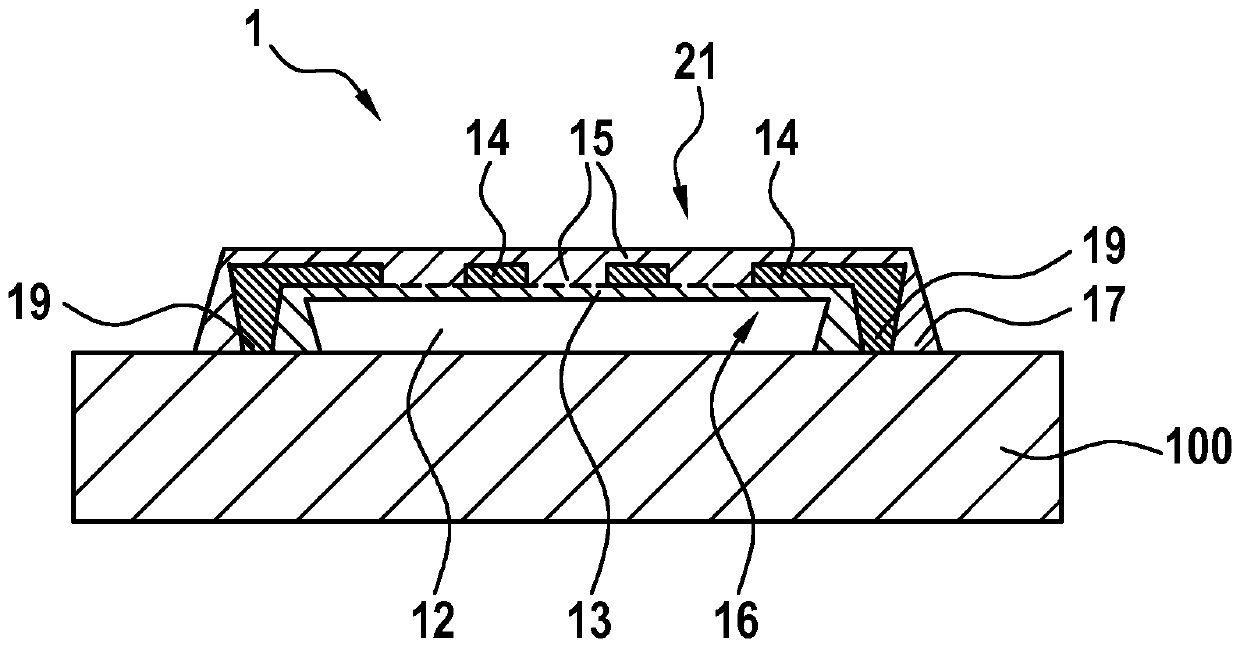
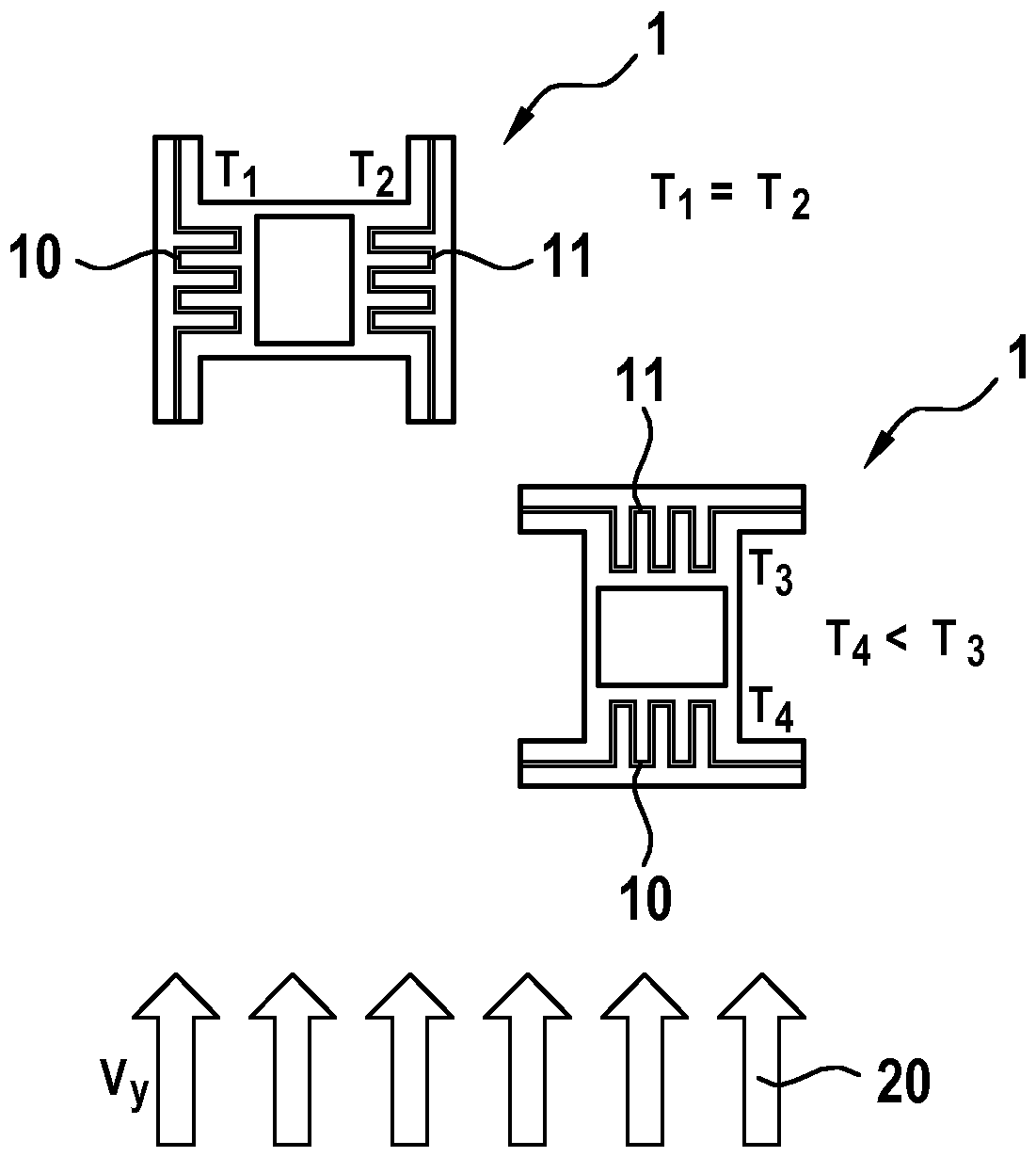
[0023] figure 1 A possible embodiment of a flow sensor 1 , which is formed on a substrate not shown, is shown by way of example. The flow sensor 1 has a carrier structure 21 which consists of multiple layers of photoresist. Two heating and temperature measuring elements 10 and 11 are accommodated in the carrier structure 21 , which are arranged spatially separated from one another and which are connected to the substrate via electrical connections 19 . The protruding electrical connection 19 is accommodated in a connecting arm 17 which is an integral part of the carrier structure 21 and which surrounds the electrical connection 19 . Centrally located between the heating and temperature measuring elements 10 , 11 is a structuring 18 , which is shown simplified as a free space.

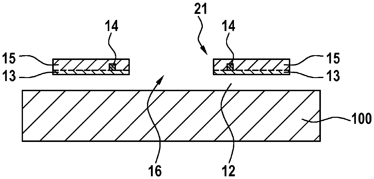
[0024] The heating and temperature measuring elements 10 and 11 are built by deposited metal 14 and have a meandering structure in the center.

[0025] figure 2 A cross-sectional view of the flow ...


PUM


Abstract

The invention relates to a method for producing a flow sensor (1) based on a thin film, having a first heater and temperature measuring element (10) and at least one second heater and temperature measuring element (11). The heater and temperature measuring elements (10, 11) are spatially separated from each other, and a support structure (21) is provided which is designed to receive the heater andtemperature measuring elements (10, 11). According to the invention, the production method has at least the following steps: providing a substrate (100); depositing a first photoresist (12) onto thesubstrate (100); depositing a second photoresist (13) onto the first photoresist (12); opening the first (12) and second photoresist (13) in order to produce a connection metallization; depositing a metal (14) in order to form the heater and temperature measuring elements (10, 11); structuring the deposited metal (14); and depositing a third photoresist (15) and removing the first photoresist (12)by means of at least one sacrificial layer etching process. The invention further relates to a flow sensor (1) produced using such a method.

Description

technical field [0001] The invention relates to a method for producing a flow sensor on a film substrate with a first heating and temperature measuring element and at least one second heating and temperature measuring element, wherein the heating and temperature measuring element They are spatially separated from one another, and wherein a carrier structure is present, which is designed to accommodate the heating and temperature measuring element. Furthermore, the invention is directed to such a flow sensor which is formed on a film substrate. Background technique [0002] Flow sensors or so-called mass flow sensors are known which operate according to the principle of a hot-wire anemometer. Here, the heating wire is kept at a constant temperature according to the closed-loop method. The stronger the surrounding mass flow (eg air flow), the more power must be supplied for this purpose in order to keep the temperature of the heating wire constant. The latter is a measure f...

Claims


Application Information

Patent Timeline
IPC IPC(8): G01F1/684G01F1/692
CPCG01F1/6845G01F1/692H10N97/00
Inventor D.格罗斯F.尤特默伦
Owner ROBERT BOSCH GMBH
Why Eureka
Try Eureka