


Quick Research
Generate reliable direction feasibility study reports for your R&D in just a few steps.

Technical Q&A
Discover and master advanced knowledge NOW. Basics, ideas, possibilities, all at once.

Find Solutions
As an expert in R&D theories, this can generate solutions to your technical problems instantly.

Evaluate Feasibility
Analyze your overall solution with one click, know your potential R&D risks in advance.

Monitor Landscape
Get weekly tech updates, stay abreast of the latest tech innovations and key insights.
Method and device for realizing fault diagnosis
A fault diagnosis and network element technology, applied in digital transmission systems, electrical components, transmission systems, etc., can solve problems such as increased complexity, inability to realize fault detection, simultaneous fault detection of multi-segment links, etc.
- Summary
- Abstract
- Description
- Claims
- Application Information
AI Technical Summary
Problems solved by technology
Method used
Image

Examples
application example 1
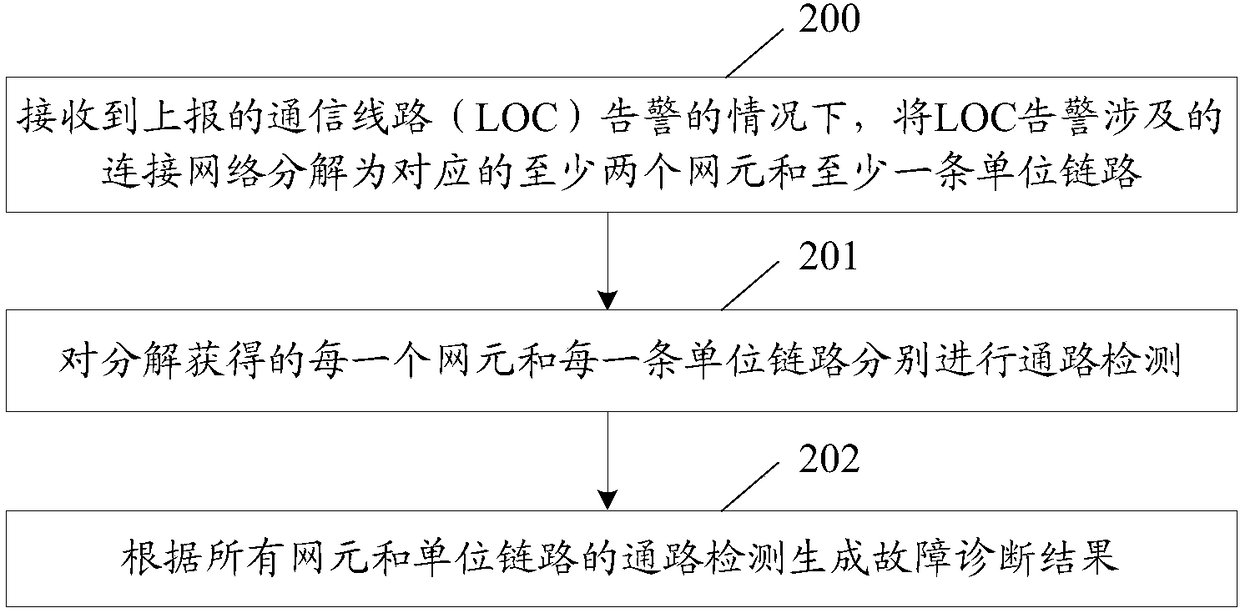
[0166] The network element in this application example does not support the outbound packet delivery function and does not include the head and tail nodes according to the version number supported by the device (for example, the version number is less than 6). The application example is used to detect the connectivity of the LSP.
[0167] Figure 9 It is the method flowchart of the first application example of the present invention, as Figure 9 shown, including:
[0168] Step 900, the controller decomposes the connection network involved in the LOC alarm into at least two corresponding network elements and at least one unit link; including: the controller decomposes the unit link that needs path detection, and the unit link can be listed as a link list The unit link is composed of two adjacent NEs: the line between the network node interface (NNI) of the outgoing port of the westbound NE and the NNI of the incoming port of the eastbound NE. One network element, the first po...
application example 2
[0177] The network element in this application example is determined by the version number supported by the device (for example, the version number is less than 6) to determine the support for the packet delivery function of the outbound port. This application example connection includes the first and last nodes. The application example is used to detect the connectivity between VPWS CIPs .
[0178] Figure 11 It is a method flowchart of the second application example of the present invention, such as Figure 11 shown, including:
[0179] This application example controller receives a LOC alarm between VPWS CIPs.
[0180] Step 1100, the controller decomposes the connection network involved in the LOC alarm into at least two corresponding network elements and at least one unit link; including: the controller decomposes the unit link that needs path detection, and the unit link can be listed as a link list The unit link is composed of two adjacent NEs: the line between the ne...
PUM
 Abstract
Description
Claims
Application Information
 - R&D Engineer
- R&D Manager
- IP Professional
- Industry Leading Data Capabilities
- Powerful AI technology
- Patent DNA Extraction
Browse by: Latest US Patents, China's latest patents, Technical Efficacy Thesaurus, Application Domain, Technology Topic, Popular Technical Reports.
© 2024 PatSnap. All rights reserved.Legal|Privacy policy|Modern Slavery Act Transparency Statement|Sitemap|About US| Contact US: help@patsnap.com