
Multi-output Scott transformer used for subway

A Scott transformer, multi-output technology, applied in the field of transformers, can solve problems such as difficulty in meeting power supply requirements

Pending Publication Date: 2018-08-21
WOLONG ELECTRIC YINCHUAN TRANSFORMER
View PDF6 Cites 0 Cited by
  • Summary
  • Abstract
  • Description
  • Claims
  • Application Information

AI Technical Summary

Problems solved by technology

However, with the gradual development of underground railways as the main form of urban communication and the continuous improvement of technology, subway locomotives have higher and higher requirements for power supply. It is difficult for conventional special transformers to meet the current special power supply requirements.

Method used


Image

  • Multi-output Scott transformer used for subway
  • Multi-output Scott transformer used for subway

Examples


Embodiment 1

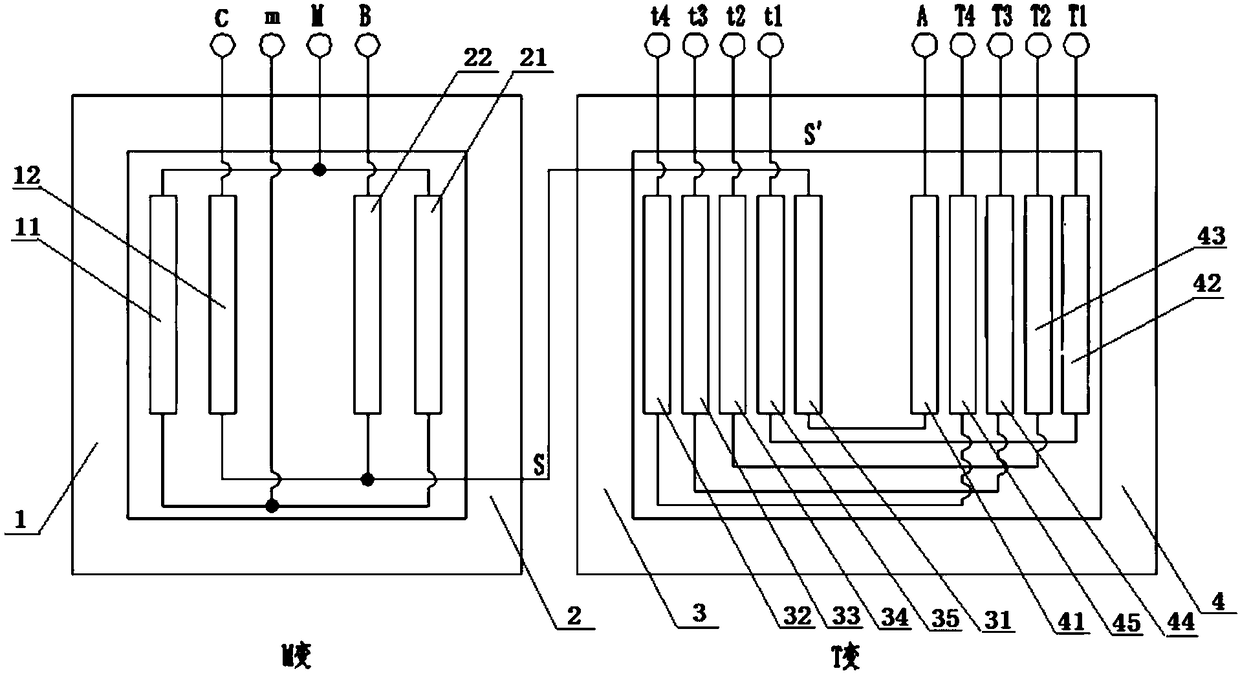
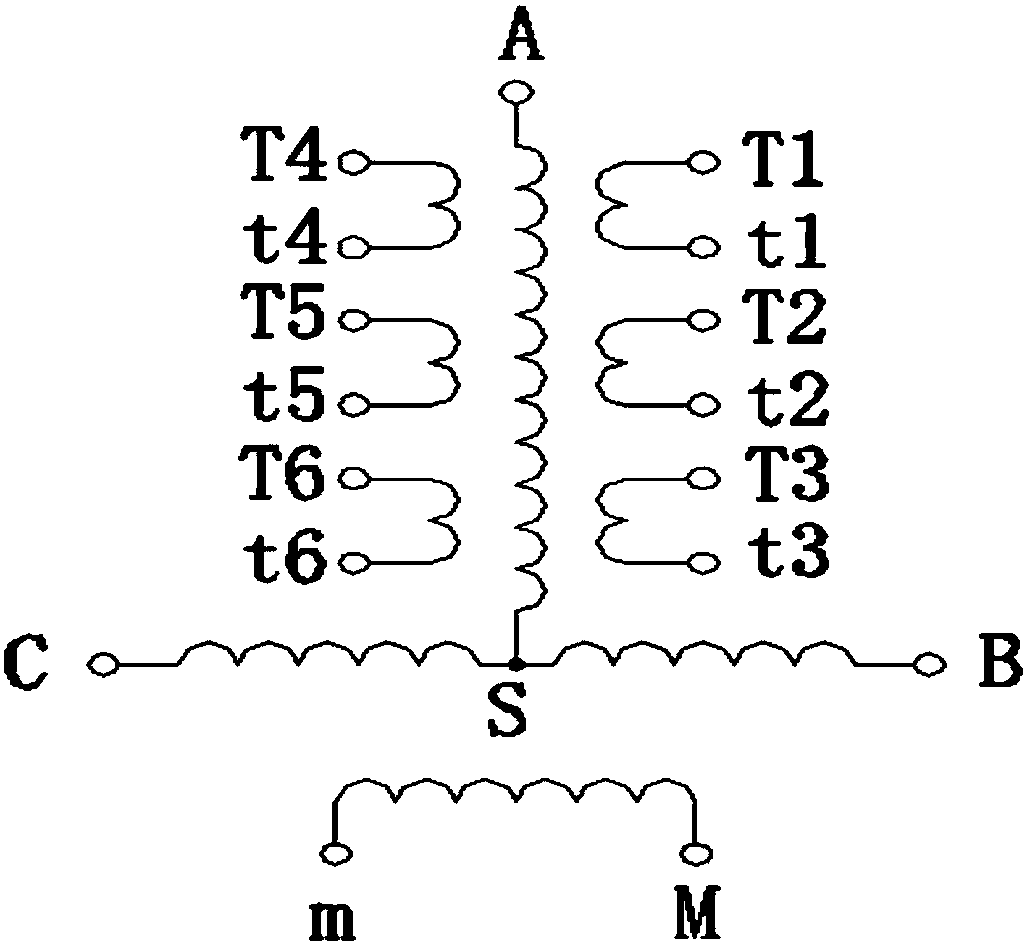
[0031] figure 1 with figure 2 Shows a structure diagram and wiring schematic diagram of a multi-output Scott transformer for subways. This example uses a transformer that transforms T to low voltage for four-winding output. Due to actual needs, the output of the low voltage winding of T can be changed Way of design.

[0032] Such as figure 1 As shown, the multi-output Scott transformer for subway provided by this embodiment includes two single-phase transformers, M-transformer and T-transformer. The M-transformer is provided with a M-transformer first main column 1 and an M-transformer second main column 2. The variant is provided with a T-variable first main column 3 and a T-variable second main column 4;

[0033] The first main column 1 of the M variable is symmetrical to the second main column 2 of the M variable. Specifically, the first main column 1 of the M variable is connected with a layer of low voltage winding (11) and a layer of high voltage winding (12) from the ins...

Embodiment 2

[0044] This embodiment is a preferred embodiment based on the first embodiment. The difference from the first embodiment is that the T-changed first main column 3 and the T-changed second main column 4 are respectively connected with 2-6 layers from the inside to the outer casing. Low-voltage winding and one-layer high-voltage winding, that is, 2≤N≤6.

[0045] In a further preferred solution of this embodiment, the first main column 3 of the T variable is connected with four layers of low voltage windings and one layer of high voltage windings from the inside to the outer casing, that is, N=4. The four-layer low-voltage windings are respectively a first-layer low-voltage winding 32, a second-layer low-voltage winding 33, a third-layer low-voltage winding 34, and a fourth-layer low-voltage winding 35. The outside of the fourth-layer low-voltage winding 35 is a high-voltage winding 31;

[0046] The second main column 4 of the T-substation and the first main column 3 of the T-substati...


PUM


Abstract

The invention discloses a multi-output Scott transformer used for a subway. The multi-output Scott transformer is formed by connecting a two-legged single-phase M transformer with a two-legged single-phase T transformer through internal wiring. The structures of two main legs of the M transformer are symmetrical, and each main leg of the M transformer comprises a layer of low-voltage winding and alayer of high-voltage winding; the structures of two main legs of the T transformer are symmetrical, and each main leg of the T transformer comprises multiple layers of low-voltage windings and a layer of high-voltage winding. The low-voltage winding of the M transformer is in parallel, and the single-phase output voltage is 27.5 kV; the low-voltage windings of the T transformer is in series, thesecond to sixth windings are preferably selected for output, and the output voltage is 3 kV. The multi-output Scott transformer used for the subway is simple and reasonable in structure, low in lossand low in cost, the three-phase current on the high-voltage side is symmetrical, two-side feeding is achieved on the low-voltage side, a multi-output way of the T transformer is implemented, and power supply requirements of urban railway subway locomotives and special power supply requirements can be met.

Description

Technical field [0001] This application relates to the technical field of transformers, in particular to a multi-output Scott transformer for subways. Background technique [0002] Electrified railway traction power supply system mainly includes direct power supply and auto transformer (AT) power supply. The shortcomings of the direct power supply method are the short power supply distance, the large number of electrical phases, and the poor power supply quality; the AT power supply mode can increase the power supply voltage, extend the power supply distance, reduce line loss, and effectively reduce the interference of the AC traction network on the communication line. There are some advantages in load power supply. [0003] Scott Transformer is a special type of transformer that can transform the three-phase power of the power supply into two-phase power (two single phases with a phase difference of 90°), provide two-phase power, and ensure the balance of the three-phase power su...

Claims


Application Information

Patent Timeline
Patent Type & Authority Applications(China)
IPC IPC(8): H01F30/14H01F27/28H01F27/30
CPCH01F27/2828H01F27/306H01F30/14
Inventor 马金山马君黄银萍曹彬
Owner WOLONG ELECTRIC YINCHUAN TRANSFORMER
Learn More