X corner point detection method applied to vision localization and calibration
A technology of corner detection and visual positioning, which is applied in the field of X corner detection, can solve the problems of large amount of algorithm calculation and not suitable for parallel batch processing, etc., and achieve the effect of enhancing robustness, improving operation speed, and improving detection speed
- Summary
- Abstract
- Description
- Claims
- Application Information
AI Technical Summary
Problems solved by technology
Method used
Image
Examples
Embodiment 1
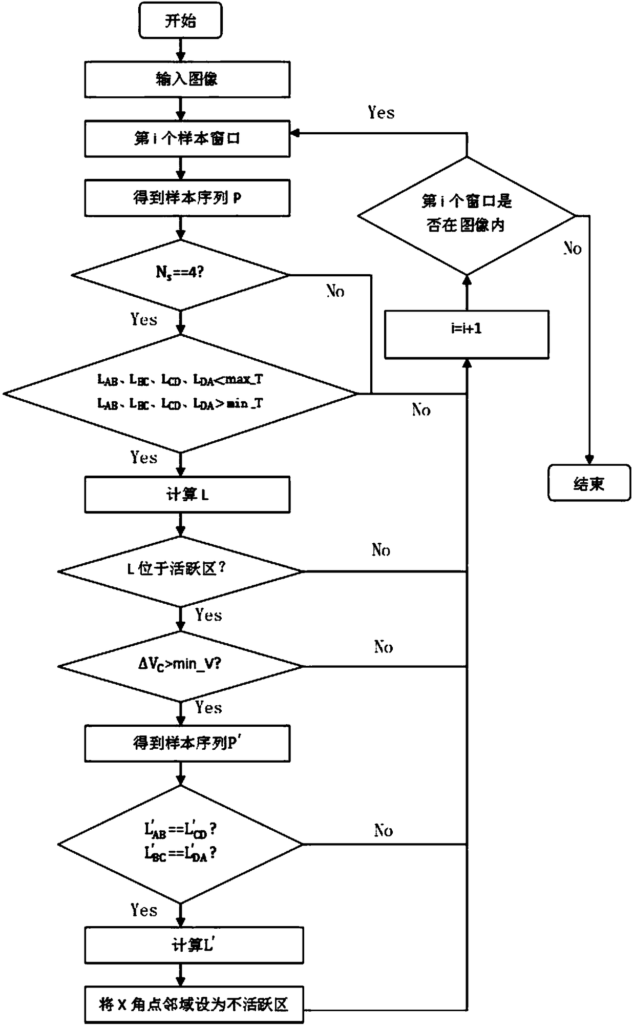
[0046] An X-corner detection method applied to visual positioning and calibration, such as figure 2 shown, including:
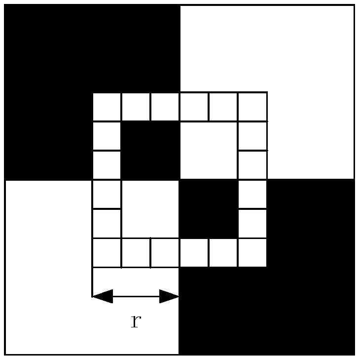
[0047] S1: Acquire images, using a paper window (such as figure 1 shown) to sample the image; set the side length of the paper-shaped window sampling to 2r pixels, and the paper-shaped window is a square, then the samples taken by the paper-shaped window contain 8r-4 pixels in total, and r is less than Half of the side length of the smallest X corner point in the image; count all the pixels of the paper window into a circular data queue, all the pixels of the paper window are the sample data P, record the i-th pixel as P i , P i The gray value of f i , i=1,2...(8r-4);
[0048] S2: According to the image characteristics of the X corner point, preliminarily judge whether the sample data P contains the X corner point, if the judgment condition is met, calculate the sub-pixel position of the X corner point, otherwise, go to step S5;
[0049] S3: According t...
Embodiment 2
[0053] According to an X corner point detection method applied to visual positioning and calibration described in Embodiment 1, the difference is that the step S2 includes:
[0054] S21: Grayscale the sample data in turn; the threshold can be selected adaptively.
[0055] S22: Binarize the gray value of the sample data twice, the binarization threshold is mean±Δ, mean is the mean value of the gray value of the sample data, Δ is the threshold adjustment value, and the value range of Δ is 20-160 pixels. The value of Δ is related to the brightness of the entire image, adding Δ as the threshold adjustment value can avoid wrong judgments caused by the influence of image noise and enhance the robustness of the algorithm. Calculate the number of steps N of the sample data processed in step S21 s , if N s =4, then execute step S23, otherwise, execute step S5;
[0056] S23: Binarize the gray value of the sample data by using the average value of the gray value of the sample data as...
Embodiment 3
[0059] According to an X corner point detection method applied to visual positioning and calibration described in Embodiment 1, the difference is that the step S3 includes:
[0060] S31: Determine the repeated detection flag of the X corner point, if the pixel value L of the X corner point obtained in step S23 is located in the inactive area, then it is determined that the X corner point has been detected, then jump out of this loop, and execute step S5; otherwise, Execute step S32;
[0061] S32: Obtain the grayscale value of the pixel value L of the X corner point neighborhood pixel, the neighborhood refers to the range with the pixel value L of the X corner point as the center and r pixels as the radius; the neighborhood grayscale value The mean of the neighborhood is used as the threshold to binarize the neighborhood, and the step number ΔV of the gray value is calculated C , if ΔV C >min_V, continue to execute step S4, otherwise, execute step S5; min_V=4.
PUM
 Abstract
Description
Claims
Application Information
 - R&D Engineer
- R&D Manager
- IP Professional
- Industry Leading Data Capabilities
- Powerful AI technology
- Patent DNA Extraction
Browse by: Latest US Patents, China's latest patents, Technical Efficacy Thesaurus, Application Domain, Technology Topic, Popular Technical Reports.
© 2024 PatSnap. All rights reserved.Legal|Privacy policy|Modern Slavery Act Transparency Statement|Sitemap|About US| Contact US: help@patsnap.com


