
A pressure pipeline crack identification method based on distributed optical fiber sensing technology

A technology of distributed optical fiber and pressure pipeline, which is applied in the direction of using optical devices to transmit sensing components, using stable tension/pressure to test the strength of materials, and analyzing materials, etc., can solve the mode aliasing, difficult to fully distributed. On-line health monitoring of structures, missed size inspections, etc., to achieve the effect of optimal layout

Inactive Publication Date: 2020-06-02
DALIAN UNIV OF TECH
View PDF10 Cites 0 Cited by
  • Summary
  • Abstract
  • Description
  • Claims
  • Application Information

AI Technical Summary

Problems solved by technology

Piezoelectric sensing technology is based on piezoelectric elements and active Lamb technology to realize structural health monitoring, but for pipelines with complex structures, a large number of Lamb wave reflection signals will be generated during measurement, and the superposition of these reflection signals will lead to serious mode aliasing , so that the cracks cannot be accurately identified, which directly affects the monitoring effect
Acoustic emission technology is only suitable for monitoring cracks that are cracking or expanding. When the structure has large-scale defects in areas with less stress, it will lead to missed inspections
Fiber Bragg grating sensors based on fiber optic sensing technology are limited by the bandwidth of incident light, and fiber Bragg grating sensors have fewer measuring points. In the field of distributed multi-point detection, it is difficult to achieve fully distributed online health monitoring of structures, and may lead to missed detection

Method used


Image

  • A pressure pipeline crack identification method based on distributed optical fiber sensing technology
  • A pressure pipeline crack identification method based on distributed optical fiber sensing technology
  • A pressure pipeline crack identification method based on distributed optical fiber sensing technology

Examples


Embodiment

[0038] Example: Taking a typical pipeline of an aircraft as an example, a pressure pipeline crack identification method based on distributed optical fiber sensing technology provided by the present invention can realize the identification and location of pipeline cracks. The specific steps are as follows:

[0039] Step 1: Obtain detailed information, material performance data, and damage tolerance of the tested pressure pipeline;

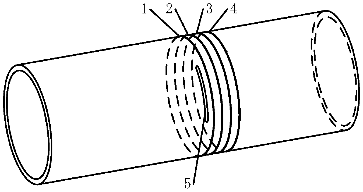
[0040] In this embodiment, a straight pipe section of a typical pipeline of an aircraft is taken, such as figure 1 As shown, the outer diameter of the pipeline is 48mm, the length is 400mm, and the thickness is 2mm. The outer surface of the pipeline has a circumferential crack with a depth of 1mm. The maximum internal pressure of the test is 10MPa; the material used for the pipeline is 304 stainless steel, and the elastic modulus of the material It is 193GPa, Poisson's ratio is 0.3, and yield limit is 207MPa;

[0041] Step 2: Perform finite element analysi...


PUM

PropertyMeasurementUnit
elastic modulusaaaaaaaaaa
Poisson's ratioaaaaaaaaaa

Abstract

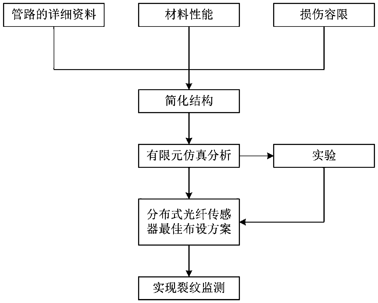
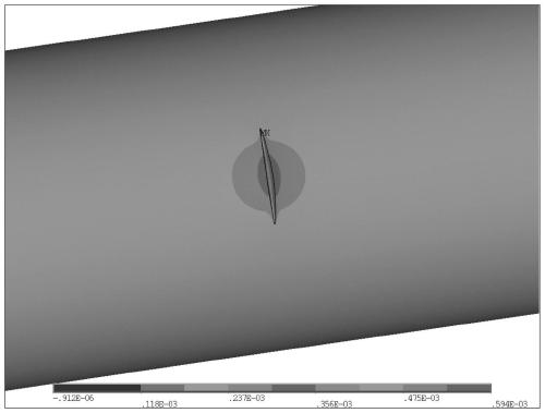
The invention discloses a pressure pipeline crack identification method based on a distributed optical fiber sensing technology. The method comprises the following steps: S1, obtaining basic data information, material performance data information and damage tolerance information of a detected pressure pipeline; S2, simplifying the pressure pipeline structure and performing finite element analysisto obtain strain distribution information near a crack; S3, determining the layout scheme of distributed optical fiber sensors according to a finite element analysis result in S2; S4, performing a hydraulic experiment on the simplified pressure pipeline structure in a laboratory, collecting strain measurement data of the sensors under different loads, and calculating the conversion coefficient ofoptical fiber segment spacing; S5, pasting the distributed optical fiber sensors arranged circumferentially in the axial direction of the outer wall of the pipeline at an interval of d according to afabrication completion drawing of the pressure pipeline and the layout scheme of the distributed optical fiber sensors in S3 for real-time monitoring of the crack.

Description

Technical field [0001] The invention relates to the technical field of structure monitoring, and in particular to a pressure pipeline crack identification method based on distributed optical fiber sensing technology. Background technique [0002] Piping system is an important system for transmitting working fluid in industrial equipment. For example, fuel system of aircraft, braking system of vehicle and drainage system of ship, etc., all require complicated piping system to transport fluid medium. During service, due to higher pipeline pressure and larger flow pulses, there is usually hydraulic shock accompanied by high-frequency pressure oscillations. Therefore, the pressure piping system is prone to cracks. Failure to identify and locate pipeline cracks in a timely and accurate manner may result in pipeline rupture and major safety accidents. [0003] At present, the main technologies used for pipeline crack monitoring in the field of structural health monitoring include: piez...

Claims


Application Information

Patent Timeline
Patent Type & Authority Patents(China)
IPC IPC(8): G01N3/08G01B11/00G01D5/353
CPCG01B11/00G01D5/353G01N3/08G01N2201/0826G01N2203/006
Inventor 周震寰袁紫衣单一男武湛君徐新生
Owner DALIAN UNIV OF TECH
Learn More