
Tunnel-type sputtering film-plating machine

A coating machine and tunnel technology, applied in the field of tunnel sputter coating machine, can solve the problems of limited capacity increase, long line of coating machine, cross-contamination of target materials, etc., to achieve improved purity, low equipment cost, continuous high productivity

Pending Publication Date: 2018-08-21
VITALNK IND SHENZHEN +1
View PDF0 Cites 0 Cited by
  • Summary
  • Abstract
  • Description
  • Claims
  • Application Information

AI Technical Summary

Problems solved by technology

[0002] In the field of coating, the currently used high-speed coating machine has a long line length, takes up a lot of space, and has high cost. There are also problems such as small chamber hang-up, low production capacity, long evacuation time, long heating time and limited increase in production capacity. There is even the problem of cross-contamination between different types of targets

Method used


Image

  • Tunnel-type sputtering film-plating machine
  • Tunnel-type sputtering film-plating machine
  • Tunnel-type sputtering film-plating machine

Examples


Embodiment Construction

[0023] In order to facilitate the understanding of the present invention, the present invention will be described more fully below with reference to the associated drawings. Preferred embodiments of the invention are shown in the accompanying drawings. However, the present invention can be embodied in many different forms and is not limited to the embodiments described herein. On the contrary, these embodiments are provided to make the understanding of the disclosure of the present invention more thorough and comprehensive.

[0024] It should be noted that when an element is referred to as being “fixed” to another element, it can be directly on the other element or there can also be an intervening element. When an element is referred to as being "connected to" another element, it can be directly connected to the other element or intervening elements may also be present.

[0025] Unless otherwise defined, all technical and scientific terms used herein have the same meaning as...


PUM


Abstract

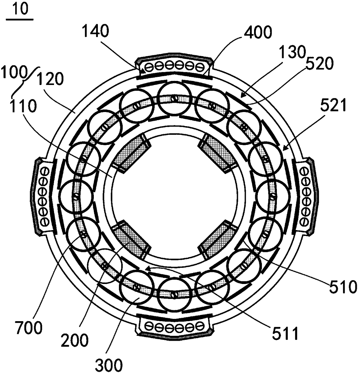
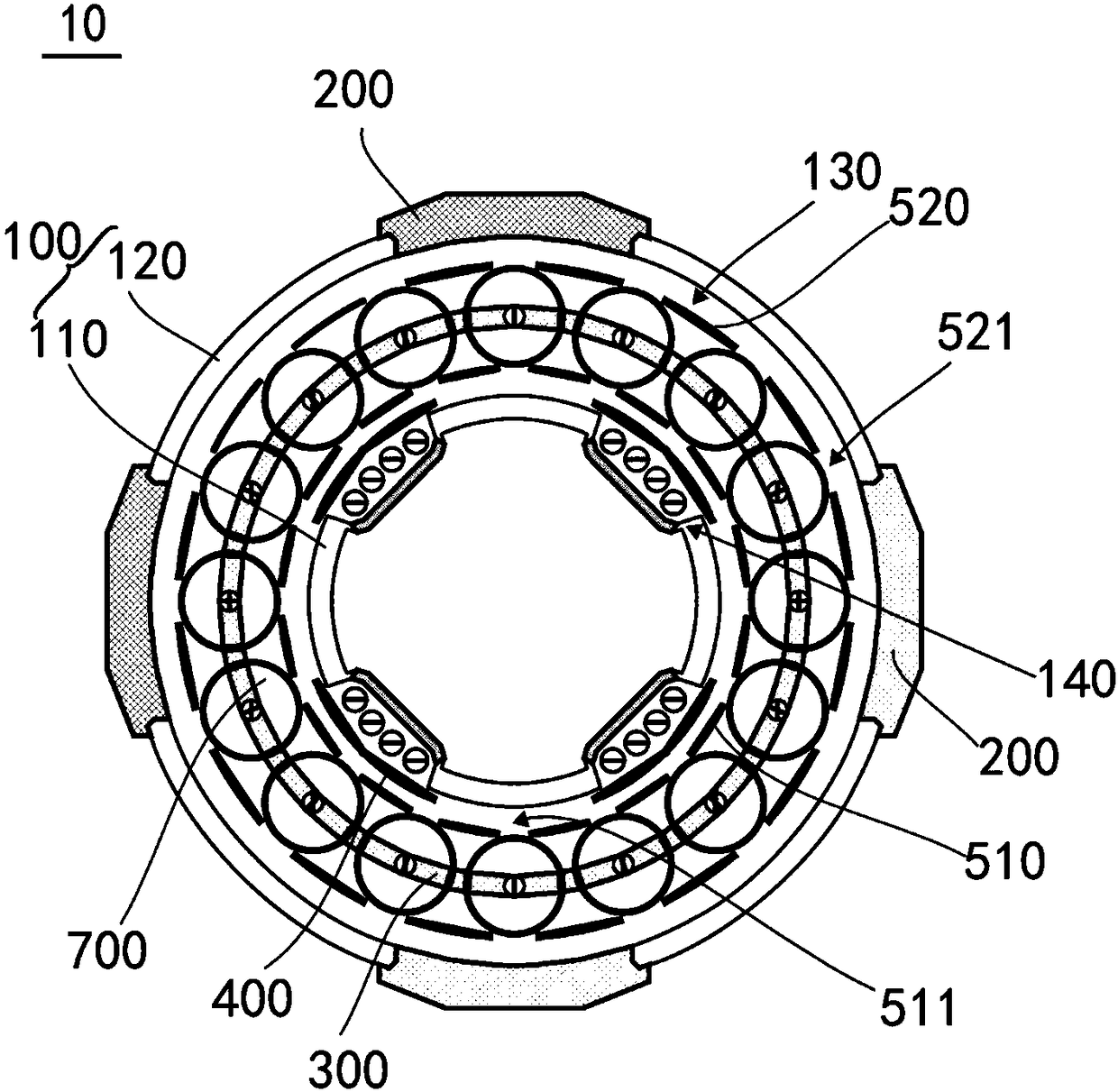
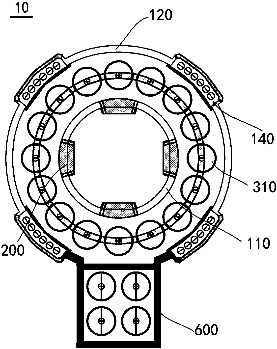
The invention discloses a tunnel-type sputtering film-plating machine. The tunnel-type sputtering film-plating machine comprises a film plating cylinder, a radio-frequency ion source, a film plating hanger, and a hanger driving device; the film plating cylinder comprises an inner cylinder and an outer cylinder; a film plating chamber is formed between the inner cylinder and the outer cylinder; thetwo ends of the inner cylinder and the two ends of the outer cylinder are correspondingly connected in a sealed manner, so that the film plating chamber is sealed; the internal wall of the outer cylinder facing the film plating chamber, or the external wall of the inner cylinder facing the film plating chamber are provided with a plurality of film plating target grooves; the radio-frequency ion source is connected with the internal wall of the outer cylinder facing the film plating chamber, or the external wall of the inner cylinder facing the film plating chamber; the film plating hanger isdesigned to be annular, and is arranged in the film plating chamber; the inner cylinder is sleeved with the film plating hanger; the film plating hanger is connected with a plurality of hanging rods;the hanging rods are arranged in an annular manner in parallel; and the hanger driving device is connected with the film plating hanger, and is used for driving the film plating hanger to rotate. Thetunnel-type sputtering film-plating machine is capable of increasing production power and efficiency effectively.

Description

technical field [0001] The invention relates to a tunnel type sputtering coating machine. Background technique [0002] In the field of coating, the currently used high-speed coating machine has a long line length, takes up a lot of space, and has high cost. There are also problems such as small chamber hang-up, low production capacity, long evacuation time, long heating time and limited increase in production capacity. There is even the problem of cross-contamination between different types of targets. Contents of the invention [0003] Based on this, it is necessary to provide a tunnel-type sputtering coater capable of effectively improving productivity and efficiency. [0004] A tunnel-type sputtering coating machine, comprising a coating tube, a radio frequency ion source, a coating hanger and a hanger driving part, the coating tube includes an inner cylinder and an outer cylinder, and there is a gap between the inner cylinder and the outer cylinder And the gap forms...

Claims


Application Information

Patent Timeline
IPC IPC(8): C23C14/34C23C14/50
CPCC23C14/3442C23C14/3464C23C14/505
Inventor 李可峰许仁符东浩虞文韬王伟
Owner VITALNK IND SHENZHEN
Learn More