
Method for visual detection of defects of light guide plate of two-side light-incoming type

A technology of visual inspection and light guide plate, applied in the field of computer vision, can solve problems such as difficult implementation of embedded systems, poor working environment, and poor eyesight of employees

Active Publication Date: 2018-08-17
杭州衡眺科技有限公司
View PDF13 Cites 14 Cited by
  • Summary
  • Abstract
  • Description
  • Claims
  • Application Information

AI Technical Summary

Problems solved by technology

There are many limitations and problems in manual detection: (1) The working environment of the employees is poor, and the strong light operation is easy to make the employees' eyesight worse, which may cause the employees to suffer from occupational diseases for a long time; Defects have high requirements on the skills and experience of employees, and it is not easy for employees to master work skills; (3) Affected by employee experience, work mood fluctuations, and reduced concentration, it is not easy to intercept all product defects, resulting in product quality fluctuations; ( 4) Due to the use of human eye recognition judgments, it is difficult for auxiliary measurement tools to form quantifiable quality standards
Using Curvelet transform, non-subsampling Contourlet transform, shearlet transform, wavelet transform and multi-scale analysis technology, the operation efficiency of the algorithm cannot meet the requirements, and it is difficult to realize in the embedded system; the correct recognition rate of some surface defects is relatively low, and the accuracy cannot be satisfied Require

Method used


Image

  • Method for visual detection of defects of light guide plate of two-side light-incoming type
  • Method for visual detection of defects of light guide plate of two-side light-incoming type
  • Method for visual detection of defects of light guide plate of two-side light-incoming type

Examples


Embodiment 1

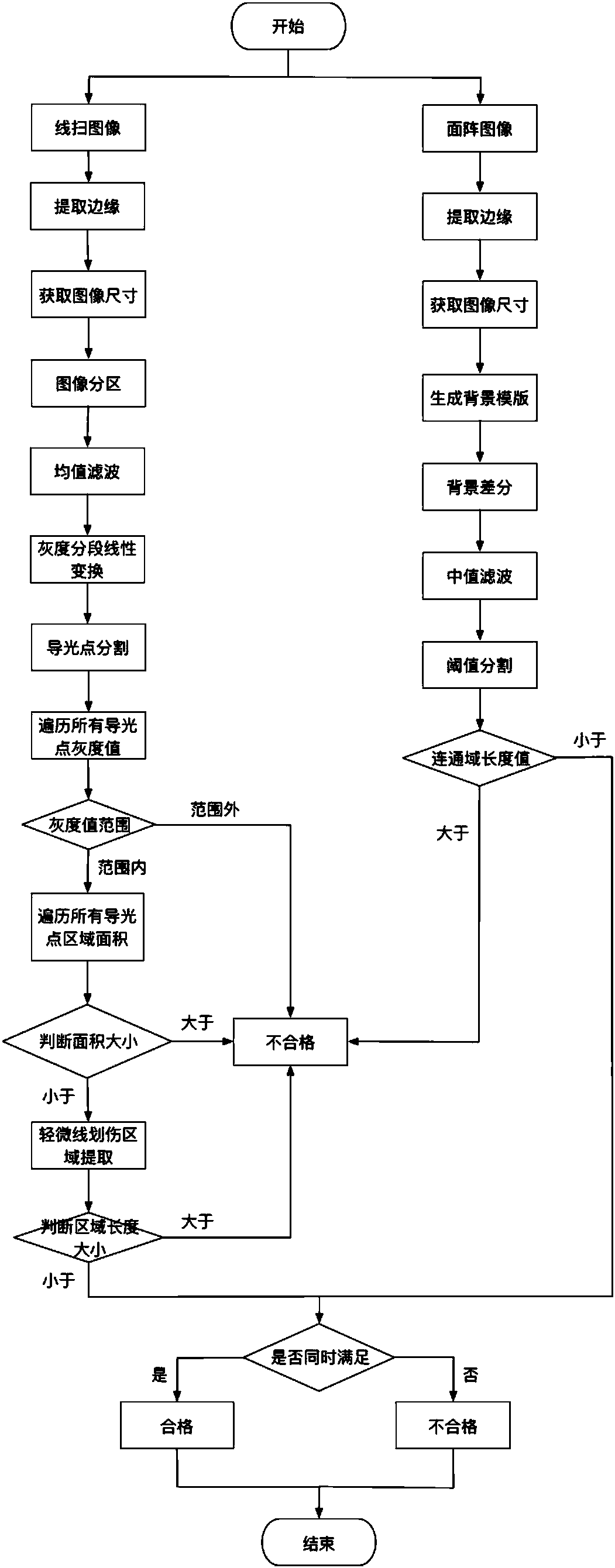
[0082] Embodiment 1. A method for visual detection of defects in a double-sided light incident type light guide plate, such as Figure 1-15 As shown, the present invention first builds a binocular inspection platform. The line scan camera is responsible for inspecting subtle defects such as scratches, crushes, bright and dark spots, and the area frame camera is responsible for detecting whether there is any shadow problem on the light guide plate after being illuminated. Secondly, for the image of the light guide plate with defects, identify the type of defect, calculate the size of the defect area, and judge whether it is qualified according to the technical requirements of different defects of the light guide plate. Finally, build an experimental platform and develop a defect detection system, and improve the accuracy, real-time and robustness of the detection system through experiments.

[0083] The specific solution is as follows:

[0084] Carry out step S1 and step 1 sim...


PUM


Abstract

The invention provides a method for the visual detection of defects of a light guide plate of a two-side light-incoming type, and the method achieves the simultaneous detection of a linear scanning gray scale image of the light guide plate and an area array gray scale image of the light guide plate. The linear scanning gray scale image of the light guide plate can be used for detecting the fine defects, such as scratches, indentations, bright and dark points. The area array gray scale image of the light guide plate can be used for detecting whether the light guide plate has a dark shadow or not after the light guide plate is irradiated by sunlight. The method is high in adaptability to the illumination changes and the type changes of the light guide plate. An area array camera and a linearscanning camera carry out the detection at the same time, thereby improving the detection precision under the condition that the detection time is not increased. The method greatly improves the detection accuracy. The method is high in operation efficiency, stability and robustness, can achieve the recognition of common defects, and has the stronger capability for detecting the unusual fine defects.

Description

technical field [0001] The invention relates to a method for extracting surface defects of a light guide plate based on machine vision technology, which belongs to the field of computer vision, in particular to a defect detection algorithm. Background technique [0002] The main material of Light Guide Plate (LGP) is optical acrylic (PMMA) plate, and its chemical name is methyl methacrylate. The transparent acrylic plate after special scientific processing, as long as it is installed on the side The illuminant (ordinary fluorescent tube, CCFL cold cathode tube, light-emitting diode and other light sources can be selected depending on the size of the light guide plate, generally installed on both sides of the length), the entire plane of the acrylic plate will emit bright, uniform and soft light after power on. Transparent acrylic sheet has high light transmittance, strong expansion and impact ability, and is widely used in the screens of various electronic products. In the ...

Claims


Application Information

Patent Timeline
IPC IPC(8): G06T7/00G06T7/11G06T7/136G01N21/88
CPCG01N21/8851G01N2021/8887G06T7/0008G06T2207/20056G06T2207/20104G06T2207/30121G06T7/11G06T7/136
Inventor 李俊峰李明睿周波朱文维柳锋
Owner 杭州衡眺科技有限公司
Learn More