Laser scanning mechanism based on lens refraction

A technology of laser scanning and mirrors, which is applied in optics, optical components, instruments, etc., can solve the problems of difficult to achieve high-speed scanning, high cost, and difficulty in improving precision, and achieve fast high-frequency continuous scanning, low cost, and simple structure Effect

Pending Publication Date: 2018-08-17
东莞市海方机电工程有限公司
View PDF0 Cites 0 Cited by
  • Summary
  • Abstract
  • Description
  • Claims
  • Application Information

AI Technical Summary

Problems solved by technology

[0003] It can be seen from the above that the current general-purpose laser scanning mainly uses the motor-driven laser transmitter to do the back-and-forth deflection action or uses the motor-driven reflector mirror to swing back and forth to realize the back-and-forth first scanning action of the laser; the light scans back and forth through the deflection mirror, which requires very precision. the rotating mechanism
At the same time, the reflective area of ​​the lens is very small, and it is difficult to improve the accuracy when converting back to the deflection angle. At the same time, the mechanical deflection mechanism is limited by the maximum speed limit of the motor, so it is difficult to achieve high-speed scanning. If the double-speed mechanism is used, the control error will inevitably increase, and the ultra-high-speed motor is used. or the drive system would add significantly to the overall cost
[0004] Therefore, the current laser scanning mechanism mainly has problems such as slow scanning speed, complex mechanical structure processing, high assembly precision requirements, poor control precision, high cost, and difficulty in realizing multi-dimensional scanning; With the rapid development of the market, there is an urgent demand for a high-speed, low-cost, and simple laser scanning mechanism

Method used


Image

  • Laser scanning mechanism based on lens refraction
  • Laser scanning mechanism based on lens refraction
  • Laser scanning mechanism based on lens refraction

Examples


Embodiment Construction

[0029] The present invention will be further described in detail below in conjunction with the accompanying drawings and specific embodiments.

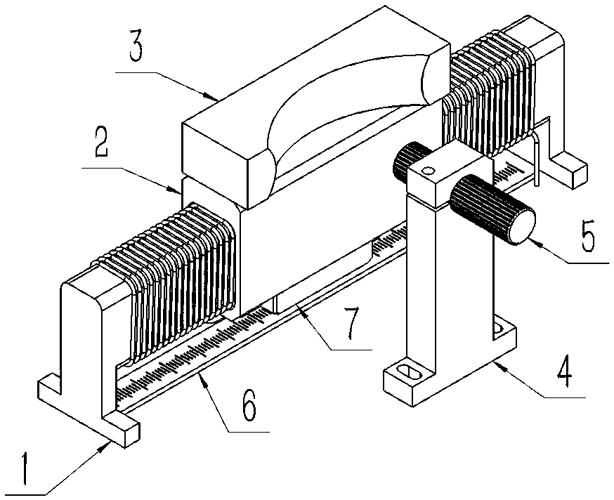
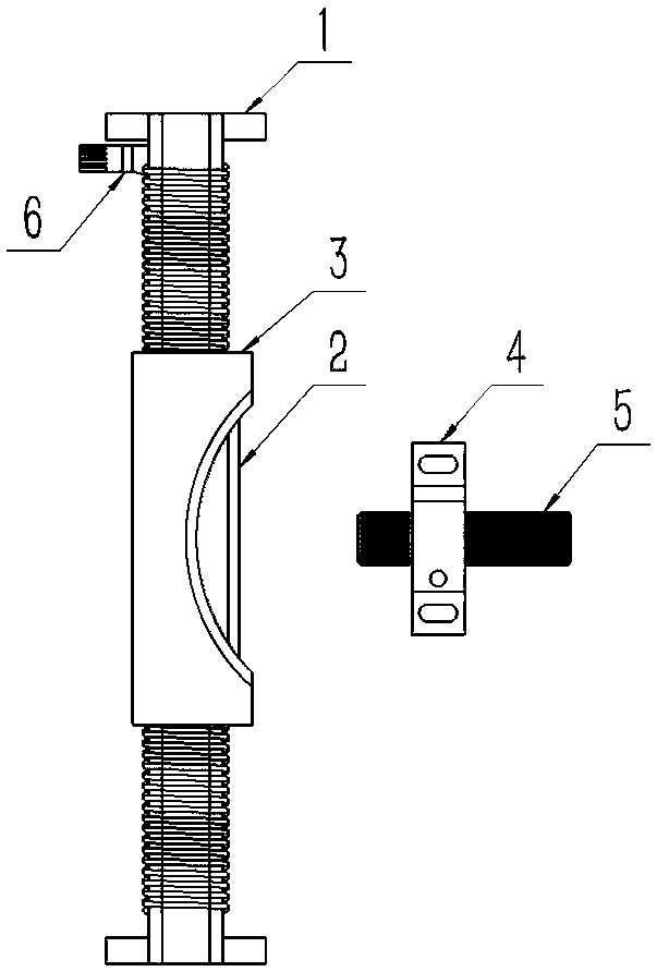
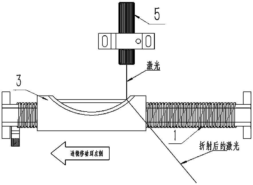
[0030] refer to Figure 1 to Figure 12 , a laser scanning mechanism based on lens refraction involved in the present invention, including a light source 5, a refracting lens 3, and a moving assembly; the light source 5 is fixed on the light source fixing seat 4, and the moving assembly includes a fixed voice coil motor stator 1 and a movable voice coil motor mover 2 arranged on the voice coil motor stator 1, the refracting lens 3 is fixed on the voice coil motor mover 2 and moves with the voice coil motor mover 2.

[0031] Specifically, in the present invention, the side of the refracting lens 3 facing the light source 5 has a concave laser incident area, and the surface of the laser incident area is a convex arc surface, which is convenient for light focusing. The laser incident area can be It is an arc-shaped concave structure, or ...


PUM


Abstract

Provided is a laser scanning mechanism based on lens refraction. The laser scanning mechanism comprises a light source, a refraction lens and a mobile assembly, the mobile assembly comprises a fixed voice coil motor stator and a movable voice coil motor rotor arranged on the voice coil motor stator, and the refraction lens is fixed on the voice coil motor rotor to move with the voice coil motor rotor. Compared with the prior art, the beneficial effects of the laser scanning mechanism based on lens refraction are that through the setting and operation of a voice coil motor, rapid and reciprocating movement of the refraction lens is realized, rapid, high-frequency and continuous scanning of laser beams is realized, the structure is simple, and the cost is low.

Description

technical field [0001] The invention belongs to the field of laser scanning equipment, and in particular relates to a laser scanning mechanism based on lens refraction. Background technique [0002] A laser scanner is an instrument that uses scanning technology to measure the size and shape of a workpiece. In the prior art, there is a rotating motor with good stability and precision in the laser scanner. When the laser source hits the beam to the The multi-faceted prism driven by the rotating motor is reflected to form a scanning beam. Since the multi-faceted prism is located on the front focal plane of the scanning lens, the rotation of the multi-faceted prism changes the incident angle of the scanning beam relatively continuously, so the reflection angle is also continuous. Change, through the action of the scanning lens, a parallel and continuous scanning line from top to bottom or from left to right is formed. [0003] It can be seen from the above that the current gene...

Claims


Application Information

Patent Timeline
IPC IPC(8): G02B26/10G02B26/08
CPCG02B26/0875G02B26/10
Inventor 贾明阳
Owner 东莞市海方机电工程有限公司
Why Eureka
Try Eureka