
A magneto-rheological valve-controlled damping stepless adjustable shock absorber

A magnetorheological valve, shock absorber technology, applied in the direction of shock absorber, shock absorber, spring/shock absorber, etc., can solve the problems of complex structure, large amount of magnetorheological fluid, large volume, etc., to avoid Mechanism redundancy, short response time, cost reduction effect

Active Publication Date: 2020-02-18
合肥庐阳科技创新集团有限公司
View PDF9 Cites 2 Cited by
  • Summary
  • Abstract
  • Description
  • Claims
  • Application Information

AI Technical Summary

Problems solved by technology

The hydraulic shock absorber uses the friction between the oil and the hole wall and the friction between the liquid molecules to form a damping force on the vibration, so that the vibration energy of the vehicle body and the frame is converted into heat energy, which is absorbed by the oil and the shock absorber shell. Then it is scattered into the atmosphere, because the damping force increases and decreases with the relative speed of the frame and the wheel, so the damping force is not controllable, let alone steplessly adjustable. When the oil leaks, the vibration damping effect becomes worse, or even disappears, and the piston wear and temperature changes will affect the vibration damping effect, the structure is complex, and the volume is large.
The magnetorheological fluid shock absorber realizes the adjustable function of the damping force to a certain extent, but the adjustable performance of the damping force is affected by the viscosity change, and the adjustment effect is not good. At the same time, the amount of magnetorheological fluid is large and the cost is high

Method used


Image

  • A magneto-rheological valve-controlled damping stepless adjustable shock absorber
  • A magneto-rheological valve-controlled damping stepless adjustable shock absorber
  • A magneto-rheological valve-controlled damping stepless adjustable shock absorber

Examples


Embodiment Construction

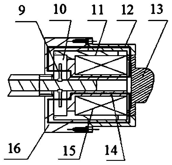
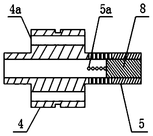
[0022] In this embodiment, the magnetorheological valve-controlled damping stepless adjustable shock absorber is composed of a magnetorheological valve-controlled unit and a hydraulic unit.

[0023] Such as figure 1 and figure 2 As shown, the structural form of the magneto-rheological valve control unit is: a piston rod 5 is set as a hollow rod body, and a plunger rod 8 coaxially arranged with the piston rod 5 is set in the hollow rod body of the piston rod 5, and can be placed in the hollow rod body. move back and forth in the axial direction; the tail end of the plunger rod 8 passes through the magnetorheological elastomer 10, and is fixedly connected with the magnetorheological elastomer support 9 arranged in the magnetorheological elastomer 10; the plunger rod 8 The front end of the front end can block the liquid flow hole 5a provided on the front end side wall of the piston rod 5 by using its side wall, and utilize the movement of the plunger rod 8 in the hollow rod bod...


PUM


Abstract

The invention discloses a magnetorheological valve control damping stepless adjustable shock absorber. The shock absorber is composed of a magnetorheological valve control unit and a hydraulic unit, and the magnetorheological valve control unit is internally provided with a piston rod which is a hollow rod body; a plunger rod sleeved in the piston rod can be axially moved in the hollow rod body; the tail end of the plunger rod is fixedly connected to a support part arranged in a magnetorheological elastomer; the open area of a flow hole in the side wall of the piston rod is changed through movement of the plunger rod, namely that the opening degree of a variable valve hole is changed; and coils are arranged and used for providing a closed magnetic field for controlling the rigidity of themagnetorheological elastomer. According to the shock absorber, the opening degree of the variable valve hole is controlled through change of the rigidity of the magnetorheological elastomer, and the output of real-time stepless controllable damping force is achieved.

Description

technical field [0001] The invention relates to a vehicle suspension vibration / shock controllable damping actuator, more specifically a magneto-rheological valve-controlled damping stepless adjustable damper. Background technique [0002] Vibration may cause structural fatigue damage to the system and related equipment, shortening the service life. For example, when a vehicle is running, it is the unevenness of the road and various inertial forces that affect its ride comfort and operational stability. The unevenness of the road is the main factor affecting the dynamic characteristics of the suspension. The excitation signal from the uneven road surface can be Divided into two categories of vibration and shock. People pay more and more attention to shock and vibration, and then the shock absorber, as the main device to control shock and vibration, develops rapidly, and the control effect of shock and vibration has been greatly improved. From the emergence of passive shock ...

Claims


Application Information

Patent Timeline
Patent Type & Authority Patents(China)
IPC IPC(8): F16F9/53F16F9/34F16F9/32
CPCF16F9/3207F16F9/3214F16F9/3221F16F9/34F16F9/535
Inventor 白先旭吴杰谭海宇沈升陈亮亮贾海涛
Owner 合肥庐阳科技创新集团有限公司
Learn More